A Step-by-Step Guide to Stereotaxic Surgery for In Vivo Extracellular Recording: Protocols, Optimization, and Best Practices
This article provides a comprehensive guide for researchers and drug development professionals on performing stereotaxic surgery for in vivo extracellular recording, a critical technique in modern neuroscience.
A Step-by-Step Guide to Stereotaxic Surgery for In Vivo Extracellular Recording: Protocols, Optimization, and Best Practices
Abstract
This article provides a comprehensive guide for researchers and drug development professionals on performing stereotaxic surgery for in vivo extracellular recording, a critical technique in modern neuroscience. It covers the foundational principles of field potential recording and electrode types, delivers a detailed methodological protocol for hippocampal surgery and recording using systems like eLab/ePulse, addresses common troubleshooting and optimization strategies to enhance animal welfare and data quality and discusses validation methods and comparative analysis with other electrophysiological techniques. The content integrates current best practices, emphasizing the 3Rs principles and methodological standards to ensure reproducible and high-quality data for preclinical research.
Understanding In Vivo Extracellular Recording: Principles and Applications in Neuroscience Research
Extracellular field potential recording represents a fundamental methodology in neuroscience for investigating brain dynamics and neuronal network activity. This application note provides researchers, scientists, and drug development professionals with a comprehensive overview of field potential fundamentals, recording methodologies, and practical applications. We focus specifically on the context of stereotaxic surgical approaches for in vivo extracellular recording, detailing the necessary instrumentation, procedural protocols, and analytical frameworks required for successful experimentation. The content emphasizes standardized protocols that enhance reproducibility while addressing key interpretive challenges associated with field potential measurements.
Understanding Field Potentials: Biophysical Basis and Significance
Local field potentials (LFPs) are transient electrical signals generated in neural tissues by the summed and synchronous electrical activity of individual cells within that tissue [1]. These signals are "extracellular" as they originate from transient imbalances in ion concentrations in the spaces outside cells resulting from cellular electrical activity. The "local" designation reflects that they are recorded by an electrode placed near the generating cells, with the inverse-square law limiting the recording to a spatially restricted radius [1].
Field potentials arise primarily from summed synaptic activity within neuronal populations. While raw extracellular recordings contain both high-frequency action potentials and lower-frequency components, LFPs are specifically extracted by low-pass filtering the signal below approximately 300 Hz [1] [2]. The unfiltered signal reflects a combination of action potentials from cells within 50-350 μm of the electrode tip and slower ionic events from within 0.5-3 mm [1]. This filtered LFP signal is believed to represent primarily the input to local neuronal networks, in contrast to spikes which represent the output from these networks [1] [2].
The geometrical arrangement of neurons significantly influences their contribution to measurable field potentials. Pyramidal cells with dendrites facing one direction and soma another (open-field configuration) produce strong dipoles when dendrites are simultaneously activated [1]. In contrast, cells with radially arranged dendrites (closed-field configuration) exhibit cancellation effects between individual dendrites and soma, resulting in minimal net potential differences [1]. This explains why certain neuronal types contribute disproportionately to recorded LFPs.
A critical consideration in LFP interpretation is that the relationship between neuronal activity and recorded signals is often counterintuitive. Research indicates that most LFP activity is not strictly local but may include remote contributions, amplitude may increase at further distances from the source, polarity does not definitively indicate excitatory or inhibitory nature, and amplitude may paradoxically increase when source activity decreases [3].
Table 1: Key Characteristics of Major Field Potential Recording Modalities
| Recording Type | Spatial Resolution | Invasiveness | Primary Applications | Neural Sources Sampled |
|---|---|---|---|---|
| Local Field Potential (LFP) | ~0.5-3 mm | High (intracerebral) | Investigating local network dynamics, synaptic inputs | Postsynaptic potentials in open-field neurons within ~250 μm-3 mm radius |
| Electroencephalography (EEG) | ~1-10 cm | Non-invasive | Clinical diagnosis, cognitive studies, sleep studies | Synchronized cortical pyramidal cell activity |
| Magnetoencephalography (MEG) | ~1-5 cm | Non-invasive | Cognitive neuroscience, presurgical mapping | Tangential currents in cortical sulci |
| Electrocorticography (ECoG) | ~0.5-1 cm | High (subdural) | Epilepsy monitoring, brain-computer interfaces | Cortical surface potentials, larger neuronal populations |
Experimental Protocol: Stereotaxic Surgery for In Vivo Hippocampal Field Potential Recording
Pre-surgical Preparation
Animal and Anesthesia: The protocol utilizes adult male Wistar rats (∼250 g) anesthetized with intraperitoneal urethane (1.6 g/kg) [4]. Maintain anesthesia with one-tenth of the initial dose as needed, confirmed by absence of tail and toe pinch withdrawal reflexes.
Surgical Setup: Sterilize all surgical instruments and the stereotaxic frame. Shave the animal's head hair and disinfect the skin with alternating scrubs of isopropyl alcohol and povidone/iodine. Apply lubricating ophthalmic ointment to prevent corneal drying. Secure the animal in the stereotaxic device using ear bars inserted into the auditory canal, confirmed by corneal blinking reflex [4].
Surgical Procedure and Coordinate Calculation
Incision and Exposure: Excise the scalp using fine scissors and gently remove periosteal connective tissue with a dental scraper to clearly expose the cranial sutures [4].
Landmark Identification: Identify bregma (intersection of sagittal and coronal sutures) and lambda (intersection of sagittal and lambdoidal sutures) using a guide cannula. Record the anterior-posterior (AP) and mediolateral (ML) coordinates of both points [4].
Coordinate Calculation: Calculate the AP difference between bregma and lambda (AP~Br~ - AP~La~). For a standard 290 g male Wistar rat, this distance should be 9.1 ± 0.3 mm. Apply a correction coefficient if the measured distance differs [4]:
For Schaffer collaterals: 9.1 / (AP~Br~ - AP~La~) = -4.2 / x
For CA1: 9.1 / (AP~Br~ - AP~La~) = -3.4 / x
Craniotomy: Mark drilling locations for Schaffer collateral (AP: -4.2, ML: +3.8) and CA1 (AP: -3.4, ML: +1.5) coordinates relative to bregma. Create four pilot holes at marked locations using a dental micromotor hand drill and perform a limited craniotomy (≈2-3 mm). Avoid the superior sagittal sinus located within 0.5 mm of the midline longitudinal suture [4].
Electrode Implantation and Recording
Electrode Placement: Use Teflon-coated stainless-steel electrodes (diameter: 0.125 mm). Position the stimulation electrode at the calculated Schaffer collateral coordinates. Gently pierce the dura mater with a sterile hypodermic needle to facilitate electrode insertion [4].
Depth Calculation: Lower the electrode slowly (1 mm every 10 seconds) to the target depth (Schaffer collaterals: DV 2.7-3.8 mm from dura; CA1: DV 4.4-5.1 mm from dura) [4].
Signal Acquisition: Connect electrodes to the eLab/ePulse electrophysiology system or equivalent. For synaptic plasticity assessment, implement input/output function, paired-pulse facilitation/depression, and long-term potentiation/depression protocols [4].
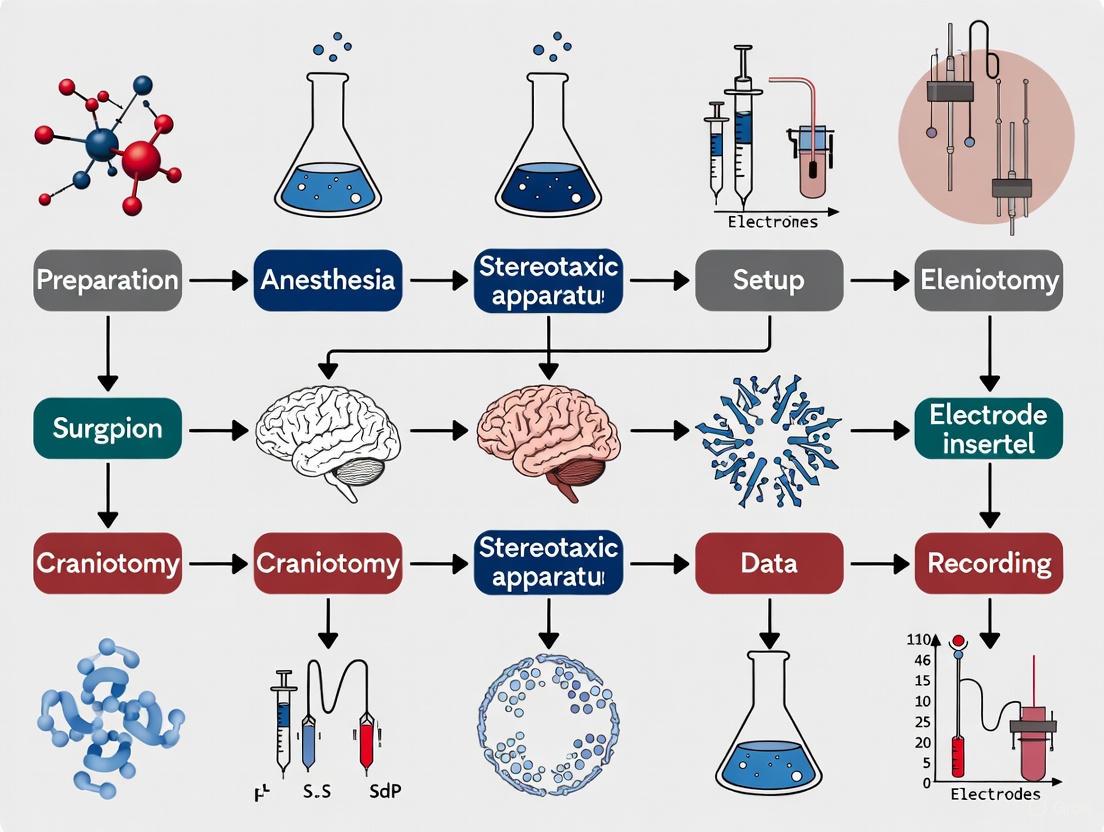
Diagram 1: Stereotaxic surgery workflow for in vivo hippocampal recording.
The Scientist's Toolkit: Essential Materials and Reagents
Table 2: Research Reagent Solutions for Stereotaxic Field Potential Recordings
| Item | Function/Application | Example Specifications |
|---|---|---|
| Anesthetics | Surgical anesthesia and pain management | Urethane (1.6 g/kg), Isoflurane, Ketamine/Xylazine mixture [4] [5] |
| Analgesics | Post-operative pain control | Buprenorphine (0.05-0.1 mg/kg) [5] |
| Microelectrodes | Neural signal recording and electrical stimulation | Teflon-coated stainless steel (0.125 mm), Tungsten, Glass micropipettes [4] |
| Stereotaxic Apparatus | Precise electrode positioning in 3D space | Digital stereotaxic with micromanipulators (Kopf model 940) [4] |
| Electrophysiology System | Signal acquisition, processing, and stimulation | eLab/ePulse system, Nanoject II injector [4] |
| Bone Anchoring | Secure electrode placement | Dental acrylic cement (Simplex Rapid) [5] |
Data Interpretation and Analytical Approaches
Relationship Between LFPs and Spiking Activity
A critical consideration in field potential research is understanding the relationship between LFPs (representing primarily synaptic inputs) and spiking activity (representing neuronal output). Studies demonstrate that entire spiking activity (ESA) - a threshold-less, continuous measure of population spiking activity - can be inferred from LFPs with good accuracy, outperforming inferences based on single-unit (SUA) or multiunit activity (MUA) [2].
The local motor potential (LMP) - the smoothed time-domain amplitude of LFP - has been identified as the most predictive feature for estimating spiking activity, consistently yielding higher inference performance compared to spectral power features across multiple frequency bands [2].
Forward and Inverse Modeling in Field Potential Research
Interpreting field potential recordings requires consideration of both forward and inverse models [6]:
Forward models describe how recorded potentials are generated by neuronal activity based on conservation of charge, Maxwell's equations, electrical properties of brain tissues, and the physics of neural sources and recording sensors [6].
Inverse models attempt to infer underlying neuronal activity from recorded potentials, though this problem is inherently ill-posed as different neuronal activity patterns can generate identical field potential measurements [6].
Table 3: Field Potential Components and Their Neural Correlates
| Signal Component | Frequency Range | Primary Neural Correlates | Analysis Approaches |
|---|---|---|---|
| Slow oscillations | <1 Hz | Up-down states, metabolic processes | Time-domain analysis, phase-amplitude coupling |
| Delta waves | 1-4 Hz | Deep sleep, pathological states | Power spectral density, event-related synchronization |
| Theta rhythm | 4-12 Hz | Hippocampal navigation, memory encoding | Phase locking, cross-frequency coupling |
| Beta waves | 12-30 Hz | Sensorimotor integration, cognitive maintenance | Coherence analysis, burst detection |
| Gamma oscillations | 30-100+ Hz | Local computation, attention, perception | Spike-field coherence, power correlations |
| Action potentials | 300-5000 Hz | Neuronal output, single-cell firing | Spike sorting, rate coding analysis |
Applications in Drug Development and Disease Modeling
Field potential recordings provide valuable platforms for pharmacological screening and disease modeling. In cardiac drug development, field potential duration (FPD) measured in microelectrode arrays (MEAs) directly correlates with action potential duration in cardiomyocytes and the QT interval in electrocardiograms [7]. This enables:
- Proarrhythmic risk assessment through FPD prolongation testing
- Cardiotoxicity screening of compound libraries using human induced pluripotent stem cell-derived cardiomyocytes (hiPSC-CMs)
- Mechanistic studies of drug effects on ion channel function
Field potential methodologies also facilitate epilepsy research through models like intrahippocampal kainic acid administration, which induces dose-dependent epileptiform activity and hippocampal pathology including granule cell dispersion and gliosis [5]. This approach offers advantages over systemic administration by targeting specific brain regions, reducing mortality, and decreasing inter-individual variability [5].
Field potential recording remains an essential technique for investigating brain dynamics in both basic neuroscience and drug development applications. When implemented through standardized stereotaxic protocols, it provides robust, reproducible data on neuronal network activity and synaptic function. However, researchers must remain mindful of the interpretive challenges associated with these signals, particularly the complex relationship between recorded potentials and their underlying neural sources. By adhering to rigorous methodological standards and employing appropriate analytical frameworks, field potential methodologies can yield valuable insights into brain function and dysfunction.
The hippocampus, a core component of the medial temporal lobe, is a primary target for in vivo electrophysiological recording due to its fundamental roles in memory processing, learning, spatial navigation, and emotions [8]. Its well-defined, layered architecture and stereotyped internal circuitry make it an ideal model system for investigating neuronal network function and synaptic plasticity. Similarly, the neocortex is organized into distinct horizontal layers, each with unique cellular composition, connectivity, and function. Understanding the anatomy and physiological properties of these structures is a prerequisite for designing and executing successful stereotaxic surgery and obtaining high-quality, interpretable neural recordings [9] [10].
This application note provides a integrated guide for researchers targeting these structures, synthesizing essential anatomical background with precise stereotaxic protocols and practical considerations for in vivo extracellular recording.
Anatomical Foundations for Recording
Functional Neuroanatomy of the Hippocampal Formation
The hippocampal formation is not a single structure but a complex of interconnected subregions. For recording purposes, understanding this intrinsic circuit is critical for accurate electrode placement and data interpretation.
- Hippocampus Proper (Cornu Ammonis): The hippocampus proper is divided into CA1, CA2, CA3, and CA4 subfields, each with distinct neuronal populations and functions [8] [11]. The large pyramidal cells in these regions are the primary sources of recorded spiking activity. The CA1 subfield is a particularly common recording site due to its clear layered organization and role as a major output node.
- Dentate Gyrus (DG): The DG serves as the input gateway to the hippocampus. It is characterized by a dense layer of granule cells [8]. These cells receive input from the entorhinal cortex via the perforant path and project mossy fibers to the CA3 subfield [8] [11].
- Trisynaptic Circuit: Information flows through the hippocampus via a classic trisynaptic loop: Perforant Path (from Entorhinal Cortex) → Dentate Gyrus Granule Cells → Mossy Fibers → CA3 Pyramidal Cells → Schaffer Collaterals → CA1 Pyramidal Cells [11]. This circuit is fundamental to hippocampal function and is a common target for plasticity studies like Long-Term Potentiation (LTP) [4].
The diagram below illustrates the major components and flow of information within the hippocampal formation relevant to recording experiments.
Laminar Organization of the Cortex
The cerebral cortex is organized into layers, each with specific cell types and connection patterns. This vertical organization creates functional units known as cortical columns [10]. When recording, the depth of the electrode determines which neuronal populations and circuits are sampled.
- Canonical Cortical Circuit: A general model of information flow describes thalamic input primarily driving neurons in Layer 4, which then project to Layer 2/3. These superficial layers subsequently project to deep layers (Layer 5 and Layer 6), which send output to other brain regions and subcortical structures [9].
- Layer-Specific Physiology: The stability and quality of neural recordings are depth-dependent. Recent studies show that Layer 4 and Layer 5 exhibit the highest spike amplitudes and the greatest long-term recording stability in the primary somatosensory cortex, while Layers 2/3 showed lower stability [10]. This has direct implications for the design and interpretation of chronic recording experiments.
Table 1: Key Hippocampal Subregions and Their Relevance to Recording
| Subregion | Primary Cell Type | Key Inputs | Key Outputs | Functional Significance for Recording |
|---|---|---|---|---|
| Dentate Gyrus (DG) | Granule Cells | Perforant Path (from Entorhinal Cortex) [8] | Mossy Fibers to CA3 [8] | Input channel; neurogenesis; pattern separation. |
| CA3 | Pyramidal Cells | Mossy Fibers (from DG) [8] | Schaffer Collaterals to CA1; Commissural to contralateral CA3 [8] [11] | Auto-association network; pattern completion. |
| CA1 | Pyramidal Cells | Schaffer Collaterals (from CA3); Direct input from Entorhinal Cortex [8] [11] | To Subiculum & Entorhinal Cortex; Alveus/Fornix [8] | Major output node; synaptic plasticity & memory. |
| Subiculum | Pyramidal Cells | CA1 [11] | Entorhinal Cortex, Fornix [11] | Interface between hippocampus and cortex. |
Stereotaxic Surgery for Hippocampal Recording
This protocol details the steps for in vivo extracellular recording of evoked field potentials in the rodent hippocampus, specifically targeting the Schaffer collateral-CA1 pathway [4].
Pre-Surgical Planning and Animal Preparation
- Anesthesia: Induce anesthesia in the rodent (e.g., male adult Wistar rat, ~250 g) using intraperitoneal (i.p.) injection of urethane (1.6 g/kg). Maintain anesthesia with one-tenth of the initial dose if necessary, as assessed by the absence of tail and toe pinch withdrawal reflexes [4].
- Animal Positioning: Secure the animal in the stereotaxic device. Insert the ear bars into the auditory canal, ensuring symmetrical placement confirmed by the corneal blinking reflex. Place the incisor bar between the upper and lower jaws to stabilize the head [4].
- Surgical Site Preparation: Shave the scalp and disinfect the skin sequentially with isopropyl alcohol and povidone/iodine. Apply ophthalmic ointment to prevent dry eyes. Make a midline incision with fine scissors and clear the periosteum connective tissue from the skull using a dental scraper. Ensure the skull surface is dry and clean to clearly visualize the bregma and lambda landmarks [4].
Coordinate Calculation and Correction
The accuracy of electrode placement depends on precise coordinate determination relative to the skull landmarks.
- Landmark Identification: Locate the bregma (intersection of the sagittal and coronal sutures) and lambda (intersection of the sagittal and lambdoidal sutures) using a guide cannula. Record the Anterior-Posterior (AP) coordinates for both points [4].
- Apply Correction Coefficient (CC): Calculate the AP difference (AP~Br~ - AP~La~). Compare this value to the standard distance for your animal's strain and weight (e.g., 9.1 ± 0.3 mm for a 290 g Wistar rat). If a difference exists, apply a CC to the target coordinates from the brain atlas [4].
- Example Calculation for Schaffer Collaterals: If the target AP coordinate is -4.2 mm from bregma (from Paxinos atlas), but the measured distance between bregma and lambda is 8.3 mm instead of 9.1 mm, the corrected coordinate is calculated as: (9.1 / 8.3) = (-4.2 / x) → x ≈ -3.8 mm [4].
Table 2: Stereotaxic Coordinates for Hippocampal Recording in Rats [4]
| Target Structure | Anterior-Posterior (AP) | Mediolateral (ML) | Dorsoventral (DV) | Function in Experiment |
|---|---|---|---|---|
| Schaffer Collaterals | -4.2 mm (from Bregma) | +3.8 mm | 2.7 – 3.8 mm (from dura) | Stimulation Site: Axons from CA3 pyramidal cells that synapse onto CA1 neurons. |
| CA1 | -3.4 mm (from Bregma) | +1.5 mm | 4.4 – 5.1 mm (from dura) | Recording Site: Soma and dendrites of CA1 pyramidal cells for recording field potentials. |
Note: These are example coordinates from the Paxinos atlas and must be verified and corrected for the specific animal being used.
Craniotomy and Electrode Implantation
- Drilling: Mark the corrected coordinates for stimulation and recording sites on the skull. Use a dental micromotor hand drill to perform a small craniotomy (≈ 2-3 mm) at the marked locations. Take care to avoid damaging the superior sagittal sinus [4].
- Dura Piercing: Gently pierce the dura mater with a sterile hypodermic needle or a small hook to facilitate electrode insertion [4].
- Electrode Placement:
- Stimulation Electrode: Lower a bipolar stimulation electrode (e.g., Teflon-coated stainless-steel) into the Schaffer collaterals at a slow rate (e.g., 1 mm every 10 seconds) to the calculated DV depth [4].
- Recording Electrode: Secure the recording electrode on the contralateral arm of the stereotaxic frame. Lower it into the CA1 region at a calculated angle (e.g., 52.5 degrees) to reach the target depth [4].
- Signal Verification: Once electrodes are positioned, apply test pulses through the stimulation electrode while monitoring the response from the recording electrode in CA1. A successful placement is indicated by the characteristic profile of a field Excitatory Post-Synaptic Potential (fEPSP).
The workflow for the entire surgical and experimental procedure is summarized below.
The Scientist's Toolkit: Research Reagent Solutions
Table 3: Essential Materials and Reagents for Stereotaxic Hippocampal Recording
| Item | Specification / Example | Function / Application |
|---|---|---|
| Anesthetics | Urethane, Isoflurane [4] [5] | Induction and maintenance of surgical anesthesia for in vivo recording. |
| Analgesics | Buprenorphine [5] | Post-operative pain management to ensure animal welfare. |
| Stereotaxic Apparatus | Digital stereotaxic device with micromanipulators (e.g., Kopf, Stoelting) [4] | Precise 3D positioning of electrodes in the brain. |
| Electrodes | Teflon-coated stainless-steel electrodes (diameter: 0.125 mm) [4] | Extracellular electrical stimulation and recording of neural activity. |
| Injector | Nanoject II Auto-Nanoliter Injector [5] | Precise micro-injection of substances (e.g., kainic acid, viral vectors). |
| Brain Atlas | Paxinos and Watson Rat Brain Atlas [4] | Reference for accurate stereotaxic coordinates. |
| Data Acquisition System | eLab/ePulse electrophysiology workstation [4] | Recording of extracellular potentials and delivery of customized electrical stimulation protocols. |
Critical Experimental Considerations & Advanced Applications
Optimizing Recording Stability and Quality
Long-term recording stability is a significant challenge in chronic experiments. The cortical layer in which the electrode resides is a major determining factor.
- Depth Matters: Evidence indicates that the long-term stability of intracortical recordings varies across cortical depth. Electrode sites around L4-L5 exhibit the highest stability over 16 weeks, while sites in L2/3 and L4 are associated with a larger area of neuronal cell loss, likely contributing to signal degradation [10].
- Spike Amplitude: In the primary somatosensory cortex, spike amplitude is not uniform across layers. The highest waveform amplitudes are typically recorded from Layer 5, significantly higher than those from superficial layers (L1, L2/3) or the deepest layer (L6) [10]. Targeting these layers can improve signal quality.
Beyond Basic Recording: Correlates of Behavior and Disease
Modern neuroscience often requires linking neural activity to specific behaviors or pathological states.
- Optical Imaging: Combining chronic hippocampal windows with two-photon microscopy and genetically-encoded calcium indicators (e.g., GCaMP3) allows for optical identification and activity recording of large populations of neurons, such as place cells in behaving mice navigating a virtual environment [12].
- Disease Models: Stereotaxic intrahippocampal administration of chemoconvulsants like Kainic Acid (KA) is a standardized protocol for creating robust models of mesial temporal lobe epilepsy. This allows for the study of seizure activity and its effects on neuronal circuits, with the advantage of precise dose control and lower mortality compared to systemic administration [5].
- Oscillatory Patterns: Intracranial recordings in humans and animals reveal that cognitive tasks induce task- and frequency-dependent oscillatory activity in the hippocampus. For example, gamma band activity is often modulated during visuo-spatial memory tasks in the anterior hippocampus, while alpha/beta band activity in the posterior hippocampus correlates with cognitive load [13].
In vivo extracellular recording is a fundamental technique in modern neuroscience that enables researchers to measure the electrical activity of neurons within a living brain. At the heart of this methodology are recording electrodes, which serve as the critical interface between biological neural tissue and physical recording devices. These electrodes function by detecting the changing voltage potentials outside neurons when they generate action potentials, providing insights into neural coding, circuit dynamics, and brain-behavior relationships [14]. The development of electrode technology has progressed remarkably since the first documented use of electrical current to address neural disease in 1757, with seminal advances including Hodgkin and Huxley's first recording of action potentials from inside a nerve fiber in 1939 [15].
The evolution of electrode technology has transformed neuroscience research, progressing from single glass micropipettes in the 1950s to today's sophisticated multi-array probes [16]. This progression has been driven by the need to record from multiple neurons simultaneously while minimizing tissue damage. The establishment of the NIH Neural Prosthesis Program in 1971 significantly accelerated innovation in neural interfaces, leading to developments such as flexible interconnects for microelectrode packaging in 1973, parylene C-coated iridium wires in 1976 that enabled recordings exceeding seven months, and the introduction of silicon probes in 1988 [16]. Contemporary electrode systems now allow chronic recordings for over one year in rat models, demonstrating remarkable advances in durability and signal stability [16].
Electrode Types and Technical Specifications
Classification and Characteristics of Recording Electrodes
Recording electrodes for in vivo extracellular recording can be broadly categorized into three main types based on their materials and construction: glass micropipettes, metal microelectrodes, and silicon-based probes. Each type offers distinct advantages and limitations, making them suitable for different experimental applications and research questions.
Glass micropipettes, first used for extracellular recording in 1953, represent the earliest form of microelectrode technology [16]. These electrodes are fabricated by heating borosilicate glass capillaries and pulling them to create fine tips with diameters less than 1 micrometer, which are then filled with an electrolyte solution [14] [17]. Glass micropipettes are particularly valued for their ability to record both intracellular and extracellular signals with high fidelity. For intracellular recordings, the electrode tip is inserted through the cell membrane to measure voltage changes across the membrane during action potentials, providing information on resting membrane potential, postsynaptic potentials, and spikes through the soma [14]. For extracellular recordings, the microelectrode is positioned close to the cell surface to detect spike information from changing extracellular potential fields generated when neurons fire action potentials [14]. The primary advantage of glass micropipettes is their exceptional signal quality, though they tend to be more fragile than metal alternatives and typically allow recording from only one site at a time.
Metal microelectrodes, introduced by Hubel in 1957, marked a significant advancement with improved mechanical durability [16]. These electrodes typically consist of fine wires made from platinum, tungsten, iridium, or stainless steel, with insulation materials such as Teflon, Parylene, polyimide, or glass covering all but the tip [14] [18] [15]. Metal electrodes are predominantly used for extracellular recordings, where their robustness allows for longer implantation periods. A significant development came with the creation of the first microwire bundle by Strumwasser in 1958, which consisted of four wires and enabled recordings for up to seven days [16]. Common configurations include tetrodes, which are formed by twisting four microwires together, and microwire arrays that arrange multiple wires on a single shaft for recording multiple single units simultaneously [18]. The exposed recording site of metal electrodes can be processed to manipulate impedance, with techniques including electroplating to reduce impedance while maintaining small surface areas, though conventional electroplating may shed material during chronic recordings [18].
Silicon-based probes, first reimagined using silicon as a substrate and MEMS-based technologies by Wise in 1969, represent the most technologically advanced electrode category [15] [16]. These probes are fabricated using microfabrication techniques that enable the creation of multiple recording sites along a single shank at precisely defined intervals [15]. The Michigan array, developed in 1994, was one of the first silicon planar electrodes with multiple recording sites, allowing simultaneous recordings at multiple depths [14] [16]. More recently, polymeric microprobes have gained attention due to their flexibility, simple fabrication process, and enhanced biocompatibility [15]. Materials such as polyimide and polydimethylsiloxane (PDMS) enable probes to conform to brain structures, potentially reducing tissue damage and improving long-term signal stability [18] [15]. The most significant advantage of silicon-based and polymer probes is their ability to incorporate multiple recording sites in precise geometrical arrangements, enabling high-density recording from specific brain layers or regions.
Table 1: Comparative Analysis of Electrode Types for Extracellular Recording
| Electrode Type | Common Materials | Tip Size | Impedance Range | Primary Applications | Key Advantages | Limitations |
|---|---|---|---|---|---|---|
| Glass Micropipettes | Borosilicate glass with electrolyte fill | < 1 μm [18] | High (tens to hundreds of MΩ) [14] | Intracellular recording, extracellular single-unit recording [14] | Excellent signal quality, suitable for intracellular measurements [14] | Fragile, typically single recording site, requires precise positioning [14] |
| Metal Microelectrodes | Platinum, tungsten, iridium, stainless steel [14] [18] | 1-100 μm [15] | Medium to High (tens of kΩ to tens of MΩ) [18] | Extracellular single-unit and multi-unit recording, chronic implants [14] [18] | Durable, suitable for long-term implantation, can be configured in arrays [18] [16] | Higher impedance than plated electrodes, may cause more tissue damage [18] |
| Silicon-Based Probes | Silicon with metal recording sites [15] | 10-50 μm (site size) [15] | Low to Medium (can be optimized through design) [15] | Multi-channel recording, laminar analysis, large-scale population recording [15] [16] | Multiple recording sites, precise site geometry, can integrate electronics [15] | Rigid, may cause more tissue damage, complex fabrication [15] |
| Polymer-Based Probes | Polyimide, PDMS [15] | 10-50 μm (site size) [15] | Similar to silicon probes [15] | Chronic recording, recording from delicate structures [18] [15] | Flexible, conforms to tissue, reduced immune response [18] [15] | May require rigid inserters for implantation, relatively new technology [15] |
Electrode Impedance and Recording Characteristics
The impedance of recording electrodes plays a critical role in determining signal quality and stimulation capability. Microelectrodes typically have impedances ranging from tens of kΩ to tens of MΩ, depending on their material, exposed surface area, and electroplating treatments [18]. Higher impedance electrodes generate more thermal noise, which follows the relationship that noise increases as a function of electrode impedance [18]. For stimulation applications, impedance determines the voltage required to deliver a specific current, with higher impedance electrodes requiring higher voltages for the same current output according to Ohm's law [18].
Electrode impedance is particularly important for distinguishing single-unit activity. A "single unit" is defined as a single, firing neuron whose spike potentials are distinctly isolated by a recording microelectrode [14]. Lower impedance electrodes generally provide better signal-to-noise ratios but record from a larger tissue volume, potentially capturing activity from multiple neurons. Conversely, higher impedance electrodes are more selective for individual neurons but may yield smaller signal amplitudes [18]. This trade-off must be carefully considered based on experimental objectives.
Table 2: Electrode Impedance and Application Guidance
| Impedance Range | Recording Characteristics | Suitable Applications | Stimulation Considerations |
|---|---|---|---|
| Low (tens of kΩ) | Lower thermal noise, larger recording volume, potentially more multi-unit activity [18] | Population recording, stimulation, recording in noisy environments [18] | Lower voltage required for stimulation, larger water window [18] |
| Medium (hundreds of kΩ to 1 MΩ) | Balance of signal-to-noise ratio and unit isolation [18] | General purpose single-unit recording, chronic implants [18] | Moderate stimulation capabilities [18] |
| High (>1 MΩ) | Better unit isolation, smaller signal amplitudes, higher thermal noise [18] | Well-isolated single-unit recording, small neuron recording [18] | Higher voltage required for stimulation, smaller water window [18] |
Stereotaxic Surgery for Electrode Implantation
Preoperative Planning and Anesthesia
Successful in vivo extracellular recording begins with meticulous surgical planning and execution. The stereotaxic surgery procedure enables precise targeting of specific brain regions through a coordinated series of steps. Before surgery, researchers must select appropriate coordinates based on a standard brain atlas such as Paxinos and Franklin's, with adjustments for individual animal variability [4] [19]. For rat hippocampal recordings, common targets include Schaffer collaterals (approximately -4.2 mm AP, +3.8 mm ML, 2.7-3.8 mm DV from dura) and CA1 (approximately -3.4 mm AP, +1.5 mm ML, 4.4-5.1 mm DV from dura) [4].
Anesthesia induction represents the first surgical step, typically using urethane (1.6 g/kg intraperitoneally for rats) or isoflurane delivered via an anesthesia induction box [4] [5]. Anesthesia depth must be continuously monitored throughout the procedure using tail and toe pinch withdrawal reflexes, with supplemental anesthesia (one-tenth of the initial dose) administered as needed [4]. Proper anesthetic management is critical as it directly impacts neuronal activity; studies show that under 2% isoflurane anesthesia lowers noise levels in neurological recordings compared to awake states, though awake recordings show a 14% increase in peak-to-peak voltage magnitude [14].
Once anesthetized, the animal is secured in a stereotaxic frame by inserting ear bars into the auditory canals and placing the incisor bar between the upper and lower jaws [4] [20]. The correct position of ear bars is confirmed by observing the corneal blinking reflex [4]. The surgical site is prepared by shaving the head, scrubbing with isopropyl alcohol followed by povidone/iodine, and applying ophthalmic ointment to prevent dry eyes [4]. A midline incision exposes the skull, and connective tissue is gently removed using a dental scraper to enhance the visibility of bregma and lambda landmarks [4] [20].
Figure 1: Stereotaxic Surgery Workflow for Electrode Implantation. This flowchart outlines the key steps in surgical implantation of recording electrodes, from preoperative planning to postoperative recovery.
Coordinate Calculation and Craniotomy
Accurate coordinate calculation is essential for precise electrode placement. Using a guide cannula, the surgeon identifies and records the coordinates of bregma (the intersection of the sagittal and coronal sutures) and lambda (the intersection of the sagittal and lambdoidal sutures) [4]. The anterior-posterior difference between bregma and lambda (APBr - APLa) is calculated, and if this differs significantly from the standard atlas value (9.1 ± 0.3 for a 290g male Wistar rat), a correction coefficient must be applied to the target coordinates [4]. For example, if the measured APBr - APLa is 8.3 instead of the expected 9.1, the corrected AP coordinate for Schaffer collaterals would be -3.8 mm instead of -4.2 mm [4].
After coordinate calculation, craniotomy is performed at the marked locations using a dental drill with 0.6-0.81 mm drill bits [4] [5]. The craniotomy should be limited to a small area (approximately 2-3 mm) to minimize brain exposure and potential damage [4]. During this process, it is critical to avoid major blood vessels, particularly the superior sagittal sinus located within 0.5 mm of the midline longitudinal suture [4]. Bone debris is carefully removed using a bent cannula or curette, and the dura mater is pierced with a sterile hypodermic needle or small hook to facilitate electrode insertion [4] [20]. Throughout the procedure, the exposed brain surface must be kept hydrated with frequent application of physiological saline or artificial cerebrospinal fluid [20].
Electrode Implantation and Fixation
Electrode implantation requires steady, controlled movement to minimize tissue damage. The selected electrode (metal wire, silicon probe, or glass micropipette) is secured in the stereotaxic holder and positioned at the calculated coordinates [4]. The electrode is then slowly lowered into the brain at a rate of approximately 1 mm every 10 seconds until reaching the target depth [4]. This gradual descent allows tissue displacement and reduces the risk of bleeding or damage.
For experiments requiring both recording and stimulation, multiple electrodes can be implanted. A common configuration involves positioning a bipolar stimulation electrode in Schaffer collaterals and a recording electrode in CA1, sometimes angled at 52.5 degrees to target specific hippocampal layers [4]. Once positioned at the target depth, electrodes are secured to the skull using anchor screws and dental acrylic cement [20] [5]. The reference electrode is typically placed above the cerebellum or in contact with skull screws [20]. Proper fixation is crucial for chronic recordings, as it prevents electrode movement that could degrade signal quality or damage surrounding tissue.
The Scientist's Toolkit: Essential Materials and Equipment
Table 3: Research Reagent Solutions for Stereotaxic Surgery and Recording
| Category | Item | Specification/Composition | Function |
|---|---|---|---|
| Anesthetics and Analgesics | Urethane [4] | 1.6 g/kg for rats (intraperitoneal) | Long-lasting surgical anesthesia |
| Isoflurane [5] | 1-3% in oxygen | Inhalation anesthesia for adjustable depth | |
| Buprenorphine [5] | 0.05-0.1 mg/kg | Postoperative pain management | |
| Surgical Supplies | Stereotaxic Apparatus [4] [5] | Digital with micromanipulators | Precise 3D electrode positioning |
| Dental Drill [5] | 0.6-0.81 mm drill bits | Creating craniotomy holes in skull | |
| Dental Cement [5] | Acrylic resin (e.g., Simplex Rapid) | Securing electrodes to skull | |
| Anchor Screws [20] | Stainless steel, 0.5-1.0 mm | Providing anchoring points for dental cement | |
| Electrophysiology Equipment | Amplifier System [4] | Cathode follower with high input impedance | Signal amplification without significant voltage drop |
| Data Acquisition System [4] [5] | Analog-to-digital converter with software | Signal processing, filtering, and recording | |
| Micropipette Puller [17] [5] | Programmable multi-step pull | Fabricating glass micropipettes with consistent tips | |
| Solutions and Chemicals | Artificial CSF [4] | Ionic composition matching brain extracellular fluid | Hydrating exposed brain tissue during surgery |
| Physiological Saline [5] | 0.9% sodium chloride | Irrigation and maintaining tissue hydration | |
| Kainic Acid [5] | 2.2-20 mM in sterile saline | Chemoconvulsant for epilepsy models |
Advanced Targeting and Validation Techniques
Multi-Site Recording and Targeting Strategies
Modern neuroscience research increasingly requires simultaneous recording from multiple brain regions to understand information processing across distributed networks. Advanced targeting techniques enable implantation of electrodes in multiple structures during a single surgical session. For example, custom-built dual-electrode drives can house multiple tetrodes with optic fibers at fixed distances for simultaneous targeting of distant brain areas such as the horizontal limb of the diagonal band of Broca (HDB) and the ventral tegmental area (VTA) [19]. These multi-target implants allow researchers to investigate functional connectivity and information flow between brain regions.
When targeting multiple structures, careful trajectory planning is essential to avoid major blood vessels and minimize tissue damage. Angled approaches (e.g., 14° from vertical) may be necessary to reach midline structures while avoiding the sinus sagittalis superior [19]. For precisely targeting specific hippocampal layers, recording electrodes can be angled at 52.5 degrees to align with the anatomical organization of the hippocampus [4]. These sophisticated approaches demonstrate how electrode technology and surgical techniques have co-evolved to address increasingly complex research questions.
Post-Implantation Validation Methods
Validating electrode placement is crucial for experimental reliability and interpretation. Traditional histological reconstruction remains the gold standard but requires animal sacrifice at the experiment's conclusion, potentially wasting resources if targeting is inaccurate [19]. Recently developed in vivo localization techniques combine micro-CT scanning with MRI to verify electrode placement immediately after surgery [19]. This approach provides high-resolution information about bone landmarks from CT imaging combined with soft tissue contrast from MRI, enabling precise localization of electrodes with respect to brain anatomy without terminal procedures [19].
The validation process involves preoperative micro-CT imaging at 35-µm resolution with the animal anesthetized and positioned in a specialized isoflurane mask [19]. After electrode implantation, postoperative CT scanning at 19-µm resolution is performed, and the images are co-registered with the preoperative scan using bone landmarks [19]. The implant is segmented using intensity thresholding, allowing calculation of stereotaxic coordinates relative to bregma [19]. This technique enables researchers to adjust electrode depth using micro-drives or terminate experiments early in cases of mistargeting, potentially saving hundreds of working hours in chronic recording projects [19].
Figure 2: Electrode Selection Framework. This diagram illustrates the relationship between electrode types, their primary applications, and key technical considerations for selection.
The landscape of recording electrode technology has evolved dramatically from single wires to sophisticated multi-array probes, enabling unprecedented access to neural circuit activity. Glass micropipettes, metal microelectrodes, and silicon-based probes each offer distinct advantages for specific research applications, with the choice of electrode depending on factors such as target region, required signal quality, implantation duration, and number of simultaneous recording sites. As electrode technology continues to advance, emerging approaches including flexible polymer probes, high-density silicon arrays, and hybrid probes for simultaneous electrical and chemical monitoring promise to further expand our ability to interrogate brain function in health and disease. When combined with meticulous stereotaxic surgical techniques and appropriate validation methods, these recording technologies provide powerful tools for unraveling the complexities of neural coding and connectivity.
Electrophysiological techniques are fundamental for probing the synaptic mechanisms underlying learning and memory. Long-term potentiation (LTP) and long-term depression (LTD) represent primary experimental models for investigating synaptic plasticity, while input/output (I/O) functions provide crucial insights into basal synaptic transmission and circuit dynamics. This application note details contemporary methodologies for investigating these phenomena, with a specific focus on protocols adaptable for in vivo extracellular recording within the context of stereotaxic surgery. The content is structured to provide researchers and drug development professionals with actionable frameworks for assessing synaptic function and plasticity in both in vivo and ex vivo preparations, emphasizing the practical integration of these techniques into a coherent research pipeline.
The Scientist's Toolkit: Research Reagent Solutions
The table below catalogues essential reagents and materials critical for successful electrophysiological investigations of LTP, LTD, and I/O functions, as evidenced by recent literature.
Table 1: Key Research Reagents and Materials for Electrophysiology Studies
| Item Name | Function/Application | Specific Examples from Literature |
|---|---|---|
| Genetically Encoded Voltage Indicators (GEVIs) | High-fidelity, single-trial readout of postsynaptic voltage signals in identified neurons in vivo. |
JEDI-2Psub for recording subthreshold/suprathreshold activity in Purkinje cell dendrites [21]. |
| Optogenetic Actuators | Selective, millisecond-timescale activation of presynaptic inputs to probe synaptic connectivity and plasticity. | ChRmine-mScarlet expressed in cerebellar granule cells for all-optical synaptic plasticity assays [21]. |
| Artificial Cerebrospinal Fluid (aCSF) | Physiological solution for maintaining ex vivo brain slice and peripheral nerve viability during recordings. |
Standard aCSF containing NaCl, KCl, NaHCO₃, CaCl₂, MgSO₄, NaH₂PO₄, and glucose, oxygenated with 95% O₂/5% CO₂ [22] [23]. |
| Three-Compartment Recording Chamber | Enables differential recording and analysis of compound action potentials from specific nerve fiber populations ex vivo. |
Vaseline-sealed chamber for stable, long-lasting recordings from isolated sciatic nerve without suction electrodes [22]. |
Quantifying Synaptic Strength: Input/Output Relationships
The input/output (I/O) relationship is a foundational measurement that assesses the functional strength of a synaptic connection by plotting the presynaptic fiber volley amplitude (or stimulus intensity) against the slope or amplitude of the postsynaptic response.
Protocol: Measuring I/O Functions in the Hippocampal Circuit
This protocol, adapted from contemporary slice electrophysiology studies, outlines the steps for assessing signal throughput from cortical input to hippocampal output [23].
- Slice Preparation: Prepare 400 µm thick horizontal hippocampal slices from mice (e.g., C57/BL6, 2-4 months) using a vibratome in ice-cold, oxygenated high-sucrose, high-Mg²⁺ artificial cerebrospinal fluid (HM-aCSF) to minimize excitotoxicity.
- Slice Recovery: Transfer slices to an interface recording chamber perfused with standard oxygenated aCSF (31 ± 1°C). Allow a recovery period of 1-1.5 hours before commencing recordings.
- Electrode Placement: Position a stimulating electrode in the lateral perforant path (LPP) within the dentate gyrus outer molecular layer. Place two recording electrodes in the CA1 region: one in the stratum radiatum to record field excitatory postsynaptic potentials (fEPSPs) and another in the stratum pyramidale to record population spikes.
- Data Acquisition: Apply single-pulse stimulations (e.g., 0.3 Hz) to the LPP at increasing intensities. For each stimulus, record both the fEPSP slope (from the stratum radiatum) and the population spike amplitude (from the stratum pyramidale).
- Analysis: Plot the fEPSP slope and population spike amplitude against the corresponding stimulus intensity or fiber volley amplitude to generate the I/O curves for the direct and indirect pathways.
Data Interpretation and Key Findings
Recent investigations into the hippocampal trisynaptic circuit have revealed unexpected operational principles, which should guide the interpretation of I/O data.
Table 2: Key Quantitative Findings from Hippocampal I/O Studies
| Parameter | Finding | Implication |
|---|---|---|
| Response Latency | The indirect path (EC-DG-CA3-CA1) triggers CA1 spiking with a significantly longer delay than the direct path (EC-CA3-CA1) [23]. | The primary hippocampal circuit operates more slowly than predicted by classic models, incorporating a mobilization time for recurrent network activity. |
| Pathway Potency | The indirect path is far more potent in driving CA1 output compared to the direct monosynaptic input from EC to CA3 [23]. | Signal throughput is heavily reliant on the dentate gyrus and the amplification provided by the massive CA3 recurrent collateral system. |
| Frequency Dependence | The circuit reliably transmits theta (5 Hz) but not gamma (50 Hz) frequency input, acting as a low-pass filter [23]. | The hippocampal circuit is tuned to preferentially process specific temporal input patterns, which may be relevant for encoding episodic sequences. |
Probing Synaptic Plasticity: LTP and LTD Protocols
LTP and LTD are experience-dependent changes in synaptic efficacy, widely studied as cellular models for memory formation and erosion.
All-Optical Interrogation of Synaptic PlasticityIn Vivo
This novel approach allows for long-term, high-fidelity measurement of synaptic plasticity in awake, behaving animals by combining optogenetics and two-photon voltage imaging [21].
- Viral Injection & Expression: Co-inject viruses expressing a genetically encoded voltage indicator (e.g., JEDI-2Psub, under a CaMKII promoter for postsynaptic cell expression) and a red-shifted opsin (e.g., ChRmine-mScarlet, Cre-dependently in presynaptic neurons) into the target brain region (e.g., cerebellar vermis Lobules V/VI).
- Animal Preparation: Train and habituate mice for head-fixed experimentation on a running wheel.
- Synaptic Stimulation & Recording: In the awake mouse, selectively activate presynaptic inputs (e.g., granule cells) with optogenetic light pulses while simultaneously performing two-photon imaging of voltage signals in postsynaptic cell dendrites (e.g., Purkinje cells) at high frame rates (e.g., 440 Hz).
- Plasticity Induction: Pair presynaptic GrC activation with a sensory-evoked signal (e.g., an air puff to the whisker pad to activate climbing fibers) according to a defined timing protocol.
- Long-Term Monitoring: Repeatedly measure the amplitude of optically recorded postsynaptic potentials over hours or days to quantify the induction of long-term changes in synaptic strength, such as the observed LTP of inhibitory responses in Purkinje cells [21].
Protocol: Extracellular Recording of LTP in Hippocampal Slices
This classic ex vivo protocol remains a gold standard for mechanistic studies of LTP [24] [23].
- Baseline Recording: Following slice recovery and electrode placement in the Schaffer collateral pathway (stimulating electrode in CA3, recording electrode in CA1 stratum radiatum), record fEPSPs for at least 20 minutes using low-frequency test pulses (e.g., 0.033-0.05 Hz). Ensure a stable baseline fEPSP slope.
- LTP Induction: Apply a high-frequency stimulation (HFS) protocol to the presynaptic fibers. Common protocols include:
- Tetanus: 1-2 trains of 100 Hz stimulation for 1 second.
- Theta-Burst Stimulation (TBS): 10 bursts of 4 pulses at 100 Hz, delivered at 5 Hz (theta frequency), repeated 3-4 times.
- Post-Tetanic Recording: Resume low-frequency test stimulation for at least 60 minutes to monitor the persistence of the enhanced fEPSP slope, which defines successful LTP.
- Data Analysis: Normalize all fEPSP slopes to the average baseline value. LTP is expressed as the percentage increase in the normalized fEPSP slope during the final 10 minutes of recording compared to baseline.
Signaling Pathways and Experimental Workflows
The following diagrams, generated using Graphviz DOT language, illustrate the core synaptic pathways and a generalized experimental workflow integrating the techniques discussed in this note.
Hippocampal Trisynaptic Circuit Pathway
Integrated Electrophysiology Workflow
The precise investigation of learning and memory processes, alongside the pathological mechanisms of neurological disorders, relies heavily on advanced in vivo techniques. Stereotaxic surgery for extracellular recording provides a powerful framework for this research, enabling scientists to monitor neuronal activity in specific brain circuits during defined behaviors. Recent breakthroughs have significantly expanded the application scope of these methods, paving the way for novel therapeutic discovery.
A primary application is the precise mapping of memory formation. The newly developed technique dubbed Extracellular Protein Surface Labeling in Neurons (EPSILON) offers an unprecedented lens into the synaptic architecture of memory [25]. By focusing on AMPARs (α-amino-3-hydroxy-5-methyl-4-isoxazolepropionic acid receptors), key proteins in synaptic plasticity, EPSILON allows researchers to monitor the history of synaptic potentiation during a defined time window of memory formation [25]. When applied to mice undergoing contextual fear conditioning—a common learning paradigm—this method demonstrated a close correlation between AMPAR trafficking and enduring memory traces (engrams), providing a molecular map of where and how memories are stored [25].
Furthermore, these techniques are critical for targeting age-related memory loss and developing interventions. Research has revealed that memory decline is linked to specific, targetable molecular changes, such as disruptions in the K63 polyubiquitination process in the hippocampus and amygdala, and the age-related silencing of the IGF2 (Insulin-like Growth Factor 2) gene in the hippocampus [26]. Using precise gene-editing tools like CRISPR-dCas13 and CRISPR-dCas9 to adjust these processes has successfully improved memory performance in older animal models, highlighting the potential for guiding new treatment approaches for conditions like Alzheimer's disease [26].
The drive to understand and treat Alzheimer's disease and related dementias (ADRD) remains a central focus. The NIH currently funds a diverse portfolio of hundreds of clinical trials, including investigations into repurposed drugs and novel therapeutic candidates targeting various biological pathways beyond amyloid, such as inflammation, synaptic plasticity, and specific neurotransmitters [27]. This reflects a strategic shift towards a precision medicine approach, acknowledging the complex and varied nature of dementia, often involving multiple co-existing pathologies (mixed dementia) that require tailored interventions [27].
Experimental Protocols
Protocol: Temporoammonic Pathway (TAP) Slice Preparation and Extracellular Recording
This protocol details the preparation of ex vivo brain slices that preserve the temporoammonic pathway (TAP)—the direct input from the entorhinal cortex to the hippocampus—and the procedures for conducting extracellular recordings to investigate synaptic plasticity [28].
Before You Begin:
- Institutional Permissions: All animal procedures must follow national and institutional guidelines for animal care and be approved by the relevant Animal Care and Use Committee [28].
- Virus and Reagent Preparation:
- Stereotaxic Viral Injection Setup: Prepare sterile surgery tools (forceps, scalpel), stereotaxic apparatus, micro-syringe injector, and compounds for anesthesia and analgesia as per institutional regulations [28].
Viral Injection Steps (to be performed >1 week before recording to allow for viral expression):
- Sterilize surgical tools and the micro-syringe needle with 70% ethanol [28].
- Thaw the viral aliquot on ice and clean the micro-syringe with ethanol followed by sterile water [28].
- Anesthetize the mouse (e.g., P28 or older) and secure it in the stereotaxic frame [28].
- Perform a craniotomy and inject the virus into the entorhinal cortex using appropriate stereotaxic coordinates [28].
- Suture the wound and allow the animal to recover, giving an analgesic if required by the protocol [28].
Acute Slice Preparation and Recording:
- Prepare Solutions: Freshly prepare cutting and recording artificial cerebrospinal fluid (ACSF) solutions daily. For example, NMDG-based protective cutting solution is used for slicing and is then replaced with standard ACSF for incubation and recording [28].
- Dissection and Slicing: Rapidly extract the brain and submerge it in ice-cold, oxygenated cutting solution. Glue the brain to a vibratome stage and create angled horizontal slices (typically 300-400 µm thick) that preserve the TAP connection, using anatomical hallmarks like the medial and lateral entorhinal cortex as guides [28].
- Incubation: Incubate slices in oxygenated ACSF at around 32°C for 20-30 minutes, then maintain at room temperature for at least one hour before recording [28].
- Extracellular Recording:
- Place a slice in the recording chamber and continuously perfuse with oxygenated ACSF at 30-32°C [28].
- Position the recording electrode in the stratum lacunosum-moleculare of the CA1 hippocampal region [28].
- Place the stimulating electrode in the medial entorhinal cortex to selectively activate the TAP fibers [28].
- Apply test stimuli to evoke field excitatory postsynaptic potentials (fEPSPs). Input-output curves are generated by gradually increasing stimulus intensity [28].
- Pathway Verification:
- Pharmacological: Apply DCG-IV (1 µM), which should significantly suppress fEPSPs in the TAP but not other pathways to CA1 [28].
- Optogenetic: In virally injected slices, deliver light pulses to activate ArchT, which should hyperpolarize and suppress presynaptic terminals, leading to a reversible decrease in TAP-evoked fEPSPs [28].
The workflow for this protocol is summarized in the following diagram:
Application: Mapping Memory Engrams with EPSILON
The EPSILON technique can be integrated with behavioral studies to map synaptic changes associated with specific memories. The following workflow outlines its application in a fear conditioning experiment:
Detailed Methodology for EPSILON Application:
- Behavioral Training: Expose the subject (e.g., a mouse) to a specific learning task, such as contextual fear conditioning, where it learns to associate a neutral context with an aversive stimulus. This creates a distinct memory trace [25].
- EPSILON Labeling: At a defined time window after memory formation, apply the EPSILON technique. This involves using sequential fluorescent labeling to tag and track the movement of AMPARs in the brain regions of interest (e.g., hippocampus, amygdala) [25].
- Tissue Processing and Imaging: Prepare brain sections and use cutting-edge microscopy to illuminate the labeled AMPARs at high resolution. This reveals the synaptic architecture and history of plasticity that occurred during the memory formation window [25].
- Data Correlation and Analysis: Combine the AMPAR maps with immunohistochemical detection of immediate early gene products like cFos, a marker of recent neuronal activity. This allows researchers to correlate patterns of synaptic strengthening with the activation of specific engram neurons [25].
Research Reagent Solutions
The following table details essential reagents and materials used in the featured protocols for studying learning, memory, and neurological disorders.
Table 1: Key Research Reagents and Materials for Stereotaxic and Electrophysiology Studies
| Reagent/Material | Function/Application | Example Details/Concentration |
|---|---|---|
| AAV9-CaMKII-ArchT-GFP | Optogenetic silencing of specific neural pathways for functional validation during recording [28]. | Drives ArchT expression in excitatory neurons; used for pathway verification [28]. |
| DCG-IV (mGluR Agonist) | Pharmacological validation of the Temporoammonic Pathway (TAP) stimulation [28]. | 1 µM; suppresses TAP-originating fEPSPs [28]. |
| CRISPR-dCas13 System | RNA editing tool to manipulate molecular processes like K63 polyubiquitination in aging studies [26]. | Used to reduce K63 polyubiquitination levels in the hippocampus to improve memory [26]. |
| CRISPR-dCas9 System | Gene-editing tool to reactivate silenced genes by removing DNA methylation tags [26]. | Used to reactivate the IGF2 gene in the hippocampus to improve memory in aged rats [26]. |
| NMDG-based Protective Cutting Solution | Protects neuronal viability during the brain slicing process for ex vivo electrophysiology [28]. | High sucrose content, low Ca2+, used ice-cold for dissection and slicing [28]. |
| Artificial Cerebrospinal Fluid (ACSF) | Maintains physiological ionic environment and provides oxygen and glucose during ex vivo recordings [28]. | Contains NaCl, KCl, NaHCO3, Glucose, CaCl2, MgSO4; perfused at 30-32°C [28]. |
| AMPAR-specific Dyes (for EPSILON) | Fluorescent labeling of AMPARs to map synaptic plasticity and memory formation in vivo [25]. | Used with sequential labeling and high-resolution microscopy to track protein movement [25]. |
Recent research and development efforts have yielded significant quantitative data, from molecular studies to clinical trial pipelines, as summarized below.
Table 2: Key Quantitative Findings in Memory and Neurological Disorder Research
| Category | Key Metric | Significance/Interpretation |
|---|---|---|
| Molecular Memory Studies | K63 polyubiquitination increased in the aged hippocampus; decreasing it improved memory [26]. | Demonstrates brain-region-specific molecular pathology and a viable target for intervention. |
| NIH Clinical Trial Portfolio | 495 clinical trials for ADRD were funded by NIH as of FY24, with over 225 focused on interventions [27]. | Reflects a substantial and diverse research effort to develop preventive and therapeutic strategies. |
| NIH Drug Development Pipeline | 25+ new drug candidates from NIH programs have advanced to human trials; 5 IND applications submitted in 2024 [27]. | Shows a robust translational pipeline targeting over a dozen biological pathways beyond amyloid. |
| Therapeutic Scope | Drug candidate CT1812 targets multiple dementia types (Alzheimer's, Lewy body) by displacing toxic proteins [27]. | Highlights promise of single therapies for mixed dementia pathologies, the most common form. |
A Detailed Surgical Protocol: From Animal Preparation to Chronic Electrode Implantation
Pre-surgical planning forms the critical foundation for successful stereotaxic procedures in neuroscience research. For in vivo extracellular recording experiments, standardized protocols for anesthesia, analgesia, and aseptic technique are paramount to ensuring both animal welfare and data integrity. This application note provides detailed methodologies and quantitative guidelines for establishing a robust pre-surgical framework, specifically contextualized within a broader thesis on stereotaxic surgery for electrophysiological investigations. The protocols outlined herein synthesize current best practices with empirical data to optimize physiological stability during recordings while maintaining strict aseptic standards to prevent confounding inflammatory responses that could compromise neural device performance [29].
Anesthesia Protocols and Physiological Considerations
Comparative Analysis of Anesthetic Regimens
The selection of anesthetic agents significantly influences tissue oxygenation dynamics and neural activity patterns, potentially confounding electrophysiological recordings. Research demonstrates that anesthesia choice directly impacts tissue pO₂ levels, with isoflurane anesthesia in room air resulting in significantly higher skin pO₂ (24-27 mmHg after 10 minutes) compared to ketamine/xylazine regimens (15-16 mmHg maintained throughout) [30]. This oxygenation differential may translate to altered neural microenvironments during recording sessions.
Table 1: Quantitative comparison of anesthetic effects on physiological parameters and recording metrics
| Parameter | Isoflurane (1.5-3.5% in room air) | Ketamine/Xylazine (100/10 mg/kg) | Significance |
|---|---|---|---|
| Tissue pO₂ at 10 mins (mmHg) | 24-27 | 15-16 | p < 0.01 [30] |
| Time to peak pO₂ (mins) | 4.7 ± 0.2 to 5.2 ± 0.4 | Not applicable (stable) | N/A [30] |
| Single-unit spike rate | Baseline (∼600% lower than awake) | Not reported | p < 0.05 [29] |
| Active electrode yield | No significant difference from awake | No significant difference from awake | p > 0.05 [29] |
| Signal-to-noise ratio | Higher than awake state | Not reported | p < 0.05 [29] |
| Noise level | Nearly 50% lower than awake | Not reported | p < 0.05 [29] |
For extracellular recording applications, studies directly comparing recording performance under anesthesia versus awake conditions reveal critical considerations. While single-unit spike rates are approximately 600% higher in awake animals compared to isoflurane-anesthetized subjects, the active electrode yield (AEY) - defined as the percentage of microelectrode sites exhibiting at least one discernable single unit - shows no statistically significant difference between states [29]. This suggests that isoflurane anesthesia does not adversely affect this key metric of device performance and reliability assessment.
Recommended Anesthesia Protocol for Stereotaxic Surgery
Based on current evidence, the following protocol is recommended for stereotaxic surgeries for extracellular recording:
Induction: Place animal in induction chamber with isoflurane at 3-4% mixed with oxygen (0.5-0.8 L/min flow rate) until loss of consciousness (typically 2-3 minutes) [31] [30].
Maintenance: Reduce isoflurane to 1.5-2.5% for surgical maintenance, delivered via nose cone integrated with stereotaxic apparatus [31] [29]. Monitor depth every 10-15 minutes via pedal reflex and respiratory pattern.
Physiological Monitoring: Maintain body temperature at 35-37°C using feedback-controlled heating pad. Apply ophthalmic ointment to prevent corneal drying during prolonged procedures [31] [29].
Analgesia Strategy for Post-operative Recovery
Pre-emptive and Multimodal Analgesia Approach
Effective analgesia is essential for both animal welfare and scientific rigor, as pain-induced stress can alter neural activity and inflammatory responses that potentially confound recording data. A pre-emptive approach administered before surgical stimulus begins provides superior pain management compared to reactive dosing.
Sustained-release buprenorphine formulations offer significant advantages for stereotaxic procedures. The recommended protocol administers buprenorphine SR (0.5 mg/mL concentration) at 50μL for a 25g mouse subcutaneously pre-operatively [31]. Critical handling considerations include:
- Do not dilute the sustained-release formulation as dilution disrupts the polymer matrix and abolishes sustained efficacy
- Warm vial to 1-2 degrees below body temperature before drawing to reduce viscosity
- Use larger bore needles (17g) for drawing to overcome pressure resistance
- Employ low dead-space syringes with precise 0.01mL graduation for accurate dosing [31]
Post-operative analgesia should continue with extended-release buprenorphine formulations or traditional buprenorphine administered every 8-12 hours for at least 48 hours post-surgery, with extended monitoring for signs of discomfort.
Comprehensive Aseptic Technique Protocol
Pre-surgical Preparation and Sterile Field Establishment
Maintaining strict asepsis throughout stereotaxic procedures is critical for preventing infection-induced neuroinflammation that can compromise neural signal quality and device longevity. The following protocol establishes a comprehensive aseptic workflow:
Pre-surgical Setup:
- Sterilize all surgical surfaces with appropriate disinfectant (e.g., peroxygen-based compounds)
- Arrange sterilized instruments on sterile barrier field
- Verify sterility integrity of all single-use items
- Ensure glass bead sterilizer is pre-heated for intraoperative instrument processing [31]
Surgical Instrument Processing:
- Sterilize all reusable surgical instruments (forceps, scalpel handles, drills) in glass bead sterilizer for 30 seconds between animals
- Clean Hamilton syringes by rinsing with sterile distilled water 10 times between uses [31]
Table 2: Essential materials for stereotaxic surgery aseptic technique
| Category | Specific Items | Function | Sterilization Method |
|---|---|---|---|
| Skin Preparation | Betadine, 70% isopropyl alcohol, sterile cotton swabs | Sequential skin antisepsis | Pre-sterilized/commercial solutions |
| Surgical Instruments | Scalpel, forceps, tweezers, drill bits | Tissue manipulation and cranial access | Glass bead sterilizer (30 sec) or autoclave |
| Injection Apparatus | 10μL Hamilton syringe, automatic injector | Precise substance delivery | Distilled water rinse, sterile technique |
| Wound Closure | Wound clips, absorbable sutures | Incision apposition | Pre-sterilized commercial products |
| Environmental Control | Sterile gloves, bench protector, disinfectant spray | Contamination prevention | Single-use or chemical disinfection |
Surgical Site Preparation and Maintenance
Animal Preparation:
- Administer pre-operative analgesics and allow appropriate uptake time (15-30 minutes)
- Induce anesthesia and position in stereotaxic apparatus
- Remove hair from surgical site using electric clippers
- Perform sequential skin preparation with alternating betadine and alcohol swabs (3 cycles minimum), moving centrifugally from incision site [31]
Sterile Field Maintenance:
- Use sterile drapes to isolate surgical site
- Limit traffic in surgical area during procedure
- Perform intraoperative instrument sterilization between procedural steps
- Minimize procedure duration to reduce contamination risk
Integrated Pre-surgical Workflow for Extracellular Recording
Temporal Coordination of Anesthesia, Analgesia and Asepsis
Successful stereotaxic surgery for extracellular recording requires meticulous temporal coordination of all pre-surgical elements. The following integrated protocol ensures optimal conditions for both animal welfare and recording fidelity:
Pre-operative Period (60-30 minutes before surgery):
- Administer sustained-release buprenorphine (0.5 mg/mL, 50μL for 25g mouse)
- Prepare surgical suite with sterilized instruments
- Verify functionality of stereotaxic apparatus and physiological monitoring equipment
Immediate Pre-surgical Period (30-0 minutes before surgery):
- Induce anesthesia with 3% isoflurane in induction chamber
- Position animal in stereotaxic frame with nose cone for maintenance anesthesia
- Perform meticulous skin preparation with betadine-alcohol cycles
- Administer ophthalmic ointment and position heating pad
Intra-operative Period:
- Maintain surgical plane with 1.5-2.5% isoflurane
- Monitor physiological parameters every 10 minutes
- Implement strict aseptic technique throughout procedure
- Re-sterilize instruments as needed using glass bead sterilizer
This integrated approach minimizes confounding variables that could compromise both animal welfare and electrophysiological data quality, particularly important for long-term recording studies where inflammatory responses to infection or poorly managed pain could alter neural signals and device integration [29].
The Scientist's Toolkit: Essential Research Reagents and Materials
Table 3: Critical reagents and materials for stereotaxic surgery pre-surgical planning
| Item | Specification/Concentration | Function | Special Handling |
|---|---|---|---|
| Isoflurane | 100% liquid, pharmaceutical grade | Inhalation anesthetic | Use with scavenging system; avoid inhalation exposure |
| Buprenorphine SR | 0.5 mg/mL sustained-release | Pre-emptive analgesia | Do not dilute; warm before use; 17g drawing needle |
| Betadine solution | 10% povidone-iodine | Surgical skin antisepsis | Apply in concentric circles from incision site |
| Sterile distilled water | Pyrogen-free | Syringe cleaning between uses | Rinse 10x for Hamilton syringes [31] |
| Ophthalmic ointment | Petroleum-based | Corneal protection during anesthesia | Apply sparingly to both eyes pre-operatively |
| Glass bead sterilizer | Bench-top model | Intra-operative instrument sterilization | 30-second exposure between uses [31] |
| Hamilton syringe | 10μL volume, 26-33g needle | Precise intracerebral injections | Clean with sterile distilled water between uses [31] |
Stereotaxic surgery is an indispensable technique in modern neuroscience, enabling researchers to target specific brain regions with high precision for procedures such as drug delivery, viral vector injection, and the implantation of recording electrodes or optical fibers. The foundation of this technique rests upon a three-dimensional Cartesian coordinate system, where the positions of deep brain structures are calculated relative to standardized landmarks on the skull [32] [33]. The small size and anatomical variability of the rodent brain mean that errors of even a few hundred microns can lead to completely missing the target structure, thereby compromising experimental outcomes and data validity [34].
The two most critical landmarks on the rodent skull are bregma and lambda. Bregma is defined as the point of intersection between the sagittal suture (which runs along the midline of the skull) and the coronal suture (which curves across the skull between the frontal and parietal bones) [32] [33]. Lambda is the analogous point where the sagittal suture meets the lambdoid suture, located more posteriorly on the skull [33]. Although these points are theoretically simple to identify, in practice, their precise determination is complicated by natural anatomical variations in suture patterns between individual animals [35] [34]. A common misconception is that bregma is simply the visible intersection of the coronal and sagittal sutures; however, the authoritative Paxinos and Franklin atlases define it more rigorously as the midpoint of the curve of best fit along the coronal suture [34] [36]. This refined definition is crucial for achieving high reproducibility, yet it is often not explicitly detailed in standard atlases, leading to inconsistent measurement practices across laboratories [32] [36].
This application note provides a detailed protocol for the precise location of bregma and lambda, and the critical subsequent step of skull leveling. Adhering to this protocol is fundamental for ensuring the accuracy, reliability, and reproducibility of stereotaxic procedures in neuroscience research.
Anatomical Foundations and the Challenge of Precision
The Stereotaxic Coordinate System
The stereotaxic apparatus, a refinement of the original instrument developed by Horsley and Clarke, allows for precise navigation along three anatomical axes [32]:
- Anteroposterior (AP): The front-to-back axis.
- Mediolateral (ML): The side-to-side axis.
- Dorsoventral (DV): The up-down depth axis [33].
In rodent surgery, bregma is most frequently used as the origin point (0,0,0) for this coordinate system [32]. The lambda point is primarily used in conjunction with bregma to level the skull in the anteroposterior plane, ensuring that the DV axis is perfectly perpendicular to the skull surface [37] [33].
Quantifying the Problem of Landmark Identification
A significant body of evidence highlights that the traditional, visual method of identifying bregma is a major source of error. A study developing a new mathematical method for locating bregma found that in 44% of subjects (11 out of 25 rats), the traditional method placed the bregma point at a location that differed by 0.2 mm or more from the point determined by the more rigorous method [34]. Given that the size of many targeted brain nuclei in rodents is sub-millimeter, an error of this magnitude can be catastrophic.
Furthermore, recent investigations have identified concerning discrepancies between different brain atlases, which compound the problem of landmark identification [32] [36]. These inconsistencies underscore the imperative for a standardized and precise protocol that minimizes subjective interpretation.
Detailed Experimental Protocol: Locating Bregma, Lambda, and Leveling the Skull
Materials and Instrumentation
Table 1: Essential Equipment for Stereotaxic Surgery
| Item | Specification | Function |
|---|---|---|
| Stereotaxic Apparatus | Kopf, Stoelting, RWD, or equivalent | Rigid frame to immobilize the animal's head and allow precise 3D movement [32]. |
| Anesthesia System | Isoflurane vaporizer or injectable anesthesia | To maintain the animal in a surgical plane of anesthesia. |
| Micro-Drill | Fine tip (0.5-0.8 mm) | For creating a small craniotomy without damaging the underlying brain tissue [37] [5]. |
| Stereotaxic Probe | Fine-tip, attached to micromanipulator | For touching the skull surface to measure coordinates. |
| Heating Pad | Feedback-controlled | To maintain the animal's body temperature during surgery. |
| Dissecting Microscope | Olympus SZ61 or equivalent | To provide magnified, clear visualization of the skull sutures [5]. |
Step-by-Step Procedure
Step 1: Animal Preparation and Head Fixation
- Induce and maintain anesthesia using an approved method (e.g., isoflurane).
- Apply a lubricating ophthalmic ointment to prevent corneal drying.
- Secure the animal in the stereotaxic frame. Place the incisors over the incisor bar and gently tighten the nose clip.
- Insert the ear bars into the external auditory meatus. Apply equal pressure on both sides until the head is firmly fixed without lateral movement [37] [33].
Step 2: Surgical Exposure and Visualization
- Shave the scalp and disinfect the surgical site with alternating betadine and ethanol scrubs.
- Make a midline incision (approximately 1.5-2 cm) with a scalpel to expose the skull.
- Gently clear the skull surface of periosteum and any connective tissue using a curette or cotton swab to achieve a clear, unobstructed view of the bregma and lambda sutures [33] [5]. Use a dissecting microscope for optimal visualization.
Step 3: Precisely Locating Bregma and Lambda
- Lower the tip of the stereotaxic probe onto the skull surface directly above the approximate location of bregma.
- Using the fine adjustments on the manipulator, trace the curve of the coronal suture. The true bregma is the midpoint of the best-fit curve of the coronal suture where it is intersected by the sagittal suture [34] [36]. Do not assume it is the exact visual intersection, as sutures can be irregular.
- Record the AP, ML, and DV coordinates at this point. Set the AP and ML values to zero. Record the DV coordinate (Z-bregma).
- Raise the probe and move it posteriorly to the lambda point. Similarly, identify it as the midpoint of the curve of the lambdoid suture where it meets the sagittal suture. Record the DV coordinate at lambda (Z-lambda) [37] [33].
Step 4: Skull Leveling
- The skull is considered level in the anteroposterior plane if the absolute difference between Z-bregma and Z-lambda is less than 0.03 mm [37].
- If the difference exceeds this tolerance (|Z-bregma - Z-lambda| > 0.03 mm), the head is tilted. To correct this, carefully adjust the height of the incisor bar. Re-measure the DV coordinates at both bregma and lambda until the difference falls within the acceptable limit.
- For final verification, move the probe to a point midway between bregma and lambda, and then 0.3 mm to the left and right of this midpoint. Gently touch the skull at these two points and record their DV values. The absolute difference between these two values should also be less than 0.03 mm to confirm the skull is level in the mediolateral plane [37].
The following workflow diagram summarizes the entire surgical preparation process, from animal setup to the final verification of a level skull.
Diagram 1: Workflow for animal preparation, bregma/lambda location, and skull leveling.
Advanced Techniques and Alternative Approaches
Automated and Mathematical Methods
To overcome the subjectivity of visual landmark identification, researchers are developing more objective techniques:
- Computer Vision: A localization framework integrating a region-based convolutional network (Faster-RCNN) and a fully convolutional network (FCN) can automatically detect bregma and lambda in rodent skull images with a mean error of less than 300 μm [35]. This method is robust to variations in lighting and animal orientation.
- Mathematical Fitting: A published method involves taking a digital picture of the exposed skull and mathematically fitting a curve to the outline of the coronal suture. The bregma is defined as the intersection of this fitted curve and the brain midline, the latter delineated from the temporal ridges of the skull [34]. This approach significantly decreases stereotaxic error compared to the "old, rough method" [34].
The Scientist's Toolkit: Key Reagents and Materials
Table 2: Essential Research Reagent Solutions for Stereotaxic Surgery
| Item | Example/Specification | Function in the Protocol |
|---|---|---|
| Anesthetic | Isoflurane, Ketamine/Xylazine mix | To induce and maintain a surgical plane of anesthesia, ensuring animal welfare and immobility [5]. |
| Analgesic | Buprenorphine, Lidocaine (local) | To manage post-operative pain and provide pre-emptive analgesia, which is an ethical and regulatory requirement [5]. |
| Antiseptic | Betadine (Povidone-Iodine), 70% Ethanol | To disinfect the surgical site and prevent post-operative infection [5]. |
| Eye Ointment | Lubricating ophthalmic ointment | To prevent corneal drying and damage during prolonged anesthesia [37] [33]. |
| Dental Cement | Polymeric cement (e.g., Simplex Rapid) | To securely anchor implanted devices such as cannulas or electrode bases to the skull [5]. |
Data Presentation: Quantifying Stereotaxic Accuracy
The following table summarizes key quantitative findings from the literature regarding the precision of bregma identification and its impact on surgical outcomes.
Table 3: Quantitative Data on Bregma Location and Stereotaxic Error
| Metric | Value | Context / Method | Source |
|---|---|---|---|
| Acceptable Skull Leveling Tolerance | < 0.03 mm | Difference in DV readings between Bregma and Lambda, and between left/right points. | [37] |
| Precision of Automated Detection | Mean error < 300 μm | Detection of Bregma and Lambda using a deep learning framework (Faster-RCNN + FCN). | [35] |
| Discrepancy Rate Between Methods | 44% (11/25 animals) | Proportion of cases where old vs. new mathematical method placed Bregma ≥ 0.2 mm apart. | [34] |
| Stereotaxic Error Reduction | Significant decrease (p < 0.05) | Total stereotaxic error was reduced in all analyzed cases when using the new mathematical method for Bregma detection. | [34] |
The precise location of bregma and lambda, followed by meticulous skull leveling, is not a mere preliminary step but the very foundation of successful stereotaxic surgery. As demonstrated, inaccuracies at this initial stage are a major source of experimental error and variability. Adherence to the detailed protocol outlined here—which emphasizes the rigorous definition of bregma as the midpoint of the coronal suture's curve and enforces a strict leveling tolerance of 0.03 mm—will significantly enhance the accuracy and reproducibility of intracranial injections and implantations. For laboratories requiring the highest possible level of precision, the adoption of automated or mathematical methods for landmark identification presents a promising path toward standardizing this critical technique across the field of neuroscience.
Stereotaxic surgery is a cornerstone of modern neuroscience, enabling precise targeting of specific brain structures for interventions such as in vivo extracellular recording. The accuracy of this procedure hinges on the correct application of stereotaxic coordinates, which are typically derived from standardized brain atlases. However, multiple factors—including individual neuroanatomical variability, brain deformation during cranial window implantation, and instrument-specific biases—can introduce targeting errors. Applying a correction coefficient is therefore essential to adjust raw coordinates and achieve targeting accuracy comparable to the size of small neuronal structures, often on the scale of tens of micrometers [38]. This Application Note details a protocol for calculating and applying this correction coefficient, framed within a broader thesis on stereotaxic surgery for in vivo extracellular recording research.
Theoretical Foundation: The Need for a Correction Coefficient
The conventional method for determining stereotaxic coordinates relies on identifying skull landmarks like bregma and lambda or using intersections of cerebral vessels as reference points. A significant challenge arises when a cranial window is installed for optical imaging prior to electrode implantation. This procedure mechanically deforms the brain surface, meaning that the brain does not return to its original position after the window is removed. Consequently, coordinates obtained through pre-surgical imaging do not align with the actual position of the brain during the implantation surgery [38].
This deformation introduces a non-linear error that cannot be adequately corrected using simple linear displacement models. The solution is to establish a mathematical transformation function—a correction coefficient—that converts the pixel coordinates from functional maps (e.g., those obtained through two-photon microscopy) into accurate stereotaxic coordinates for surgical implantation.
Quantitative Comparison of Coordinate Conversion Methods
Different mathematical approaches can be used to calculate the transformation, each with varying degrees of accuracy. The following table summarizes the performance of several methods, as evaluated on the rat olfactory bulb, highlighting the superiority of the regularized quadratic approach.
Table 1: Comparison of Coordinate Conversion Methods for Stereotaxic Surgery
| Method Name | Mathematical Approach | Key Principle | Reported Accuracy (Mean Absolute Error) | Primary Advantage |
|---|---|---|---|---|
| Locally Linear (Displacement) | Linear | Calculates coordinates as a simple displacement from the nearest single reference vessel. | Lower accuracy (Not specified) | Simplicity |
| Globally Linear | Linear | Applies a single linear transformation function across the entire dorsal surface. | ~175 µm | Whole-surface consistency |
| Locally Linear (Region-based) | Linear | Constructs a unique linear function for each small region of the brain surface. | ~150 µm | Accounts for local variations |
| Globally Quadratic | Quadratic | Fits a single, more complex quadratic function to the entire dorsal surface. | ~70 µm | Models non-linear deformation |
| Globally Quadratic with L2-Regularization | Quadratic with L2 regularization | Fits a quadratic function with constraints to prevent overfitting to the reference data. | ~40 µm (Improves accuracy by 10-30 µm) | Highest accuracy and robustness [38] |
The L2-regularized quadratic method significantly outperforms others, minimizing the absolute error in determining the coordinates of points of interest. This method effectively models the smooth, non-linear nature of brain surface deformation while maintaining stability through regularization, which prevents the model from fitting to noise in the reference point data [38].
Experimental Protocol: Implementing the L2-Regularized Quadratic Method
This protocol provides a step-by-step guide for implementing the most accurate coordinate conversion method.
Materials and Equipment
Table 2: Research Reagent Solutions and Essential Materials
| Item Name | Function/Application | Specification/Example |
|---|---|---|
| Confocal/Two-Photon Microscope | To obtain high-resolution images of the brain surface through the cranial window for functional mapping. | LSM 880 (Carl Zeiss) [38] |
| Stereotaxic Frame & Injector | To perform precise cranial surgeries and electrode implantations based on calculated coordinates. | Standard rodent stereotaxic setup with micro-syringe injector [28] |
| Reference Dye or Vectors | To provide clear visual landmarks (vessel intersections) on the brain surface for registration. | N/A (Relies on intrinsic vasculature) [38] |
| Surgical Tools | For craniotomy, dura mater removal (durotomy), and implantation of cranial windows and electrodes. | Forceps, scalpel, drill, sterile supplies [28] |
| Computational Software | To perform the L2-regularized quadratic transformation and coordinate calculations. | MATLAB with custom scripts [38] |
| L2-Regularized Quadratic Algorithm | The core mathematical tool for converting pixel coordinates to stereotaxic coordinates with high accuracy. | Custom-made script [38] |
Step-by-Step Procedure
Pre-Surgical Imaging and Landmark Identification:
- Install a cranial window following established protocols [38].
- Obtain a high-resolution image of the brain surface (e.g., using two-photon microscopy) through the cranial window.
- Within the image, identify at least 6-8 reliable reference points. The intersections of cerebral vessels serve as excellent landmarks. Record the pixel coordinates for each of these points.
Establishing Ground Truth Stereotaxic Coordinates:
- With the cranial window still in place and the brain in its deformed state, use the stereotaxic apparatus to carefully lower a reference probe to each of the identified vessel intersections.
- Record the actual stereotaxic coordinates (X, Y, Z) read from the stereotaxic apparatus for each corresponding point. This set of paired data (pixel coordinates real stereotaxic coordinates) forms the ground truth dataset for building the transformation model.
Model Fitting: Calculating the Correction Function:
- Let ( (xi, yi) ) be the pixel coordinates of the (i)-th reference point, and ( (Xi, Yi, Z_i) ) be its measured stereotaxic coordinates.
- The goal is to find a function ( F ) such that ( (X, Y, Z) \approx F(x, y) ).
- For each stereotaxic axis (X, Y, Z independently), fit a quadratic function with L2-regularization. For the X-coordinate, the model is: ( X = \beta0 + \beta1x + \beta2y + \beta3x^2 + \beta4xy + \beta5y^2 + \epsilon )
- The L2-regularization adds a penalty term proportional to the square of the magnitude of the coefficients (excluding the intercept ( \beta_0 )) to the least-squares minimization problem. This penalty helps prevent overfitting, especially when the number of reference points is limited, resulting in a more robust and generalizable model [38].
Application: Converting Target Coordinates for Surgery:
- From your functional maps (e.g., calcium imaging), identify the pixel coordinates (x, y) of the target region of interest (e.g., a specific neuronal population).
- Input these pixel coordinates into the three derived quadratic functions (one for each stereotaxic axis X, Y, Z).
- The output is the corrected stereotaxic coordinates to be used for the implantation of microelectrodes, cannulas, or probes.
Diagram 1: Workflow for calculating and applying stereotaxic correction coefficients.
Quality Assurance and Validation
To ensure the reliability of the corrected coordinates, rigorous quality assurance is mandatory.
- Histological Verification: Post-experiment, perform standard histological processing (perfusion, sectioning, staining) to visualize the electrode tract or lesion site. Compare the actual location with the intended target.
- Electrophysiological Quality Control: For in vivo recordings, implement quality metrics such as neuron yield (number of quality-control-passing units per electrode site) and signal-to-noise ratio. These metrics can be compared to benchmarks from established datasets to ensure recording quality is consistent with proper targeting [39].
- RIGOR Framework: Adopt the Recording Inclusion Guidelines for Optimizing Reproducibility (RIGOR), which combines histological and electrophysiological quality-control criteria to validate that recordings are obtained from the intended target and are of sufficient quality, thereby enhancing the reproducibility of findings across laboratories [39].
Achieving high-precision targeting in stereotaxic surgery for extracellular recording requires moving beyond simple coordinate lookup. The installation of cranial windows induces non-linear brain deformation that necessitates a mathematical correction. The L2-regularized quadratic method provides a superior solution, significantly improving targeting accuracy by modeling this complex deformation while preventing overfitting. By integrating this computational approach with rigorous quality control protocols, researchers can significantly enhance the accuracy and reproducibility of their in vivo electrophysiological experiments, thereby increasing the reliability of data for both basic neuroscience and drug development.
Stereotaxic surgery for in vivo extracellular recording is a foundational technique in neuroscience research, enabling precise investigation of neural circuits, drug effects, and disease mechanisms. The craniotomy—the surgical opening of the skull—and the subsequent piercing of the dura mater are critical steps in this process. The integrity of the subsequent physiological recordings is profoundly dependent on the precision and safety of these steps. In particular, avoiding damage to the brain's vascular structures is paramount; such damage can not only compromise animal welfare and data quality through hemorrhage but also alter the local neural environment, thereby confounding experimental results. This protocol details a step-by-step methodology for performing a craniotomy and dura piercing tailored for extracellular recording research, with a central focus on techniques for identifying and preserving vascular structures [40] [5].
The success of this procedure hinges on a thorough understanding of the anatomical layers involved. The skull provides the first barrier, beneath which lies the dura mater, a tough, fibrous membrane that protects the underlying brain and encloses the arachnoid and pia maters [41]. The dura itself is a vascularized structure, and piercing it requires careful technique to avoid underlying vessels on the brain's surface. This protocol emphasizes the use of optical visualization and meticulous surgical technique to minimize trauma and ensure the collection of high-fidelity neural data [40].
The Scientist's Toolkit: Essential Materials and Equipment
Performing a precise craniotomy requires specialized equipment and reagents. The following table catalogs the essential items and their specific functions within the procedure.
Table 1: Essential Research Reagents and Equipment for Stereotaxic Craniotomy
| Item | Function/Application in Protocol |
|---|---|
| Kainic Acid (KA) | A glutamate agonist used in research models to induce neuronal excitation or epilepsy for study. It is administered via stereotaxic injection [5]. |
| Isoflurane | An inhaled anesthetic used for the induction and maintenance of general anesthesia in laboratory animals during surgical procedures [5]. |
| Buprenorphine | An analgesic administered pre- and post-operatively to manage pain and improve animal welfare in accordance with ethical guidelines [5]. |
| Sterile Saline | Used as a solvent for drugs and to maintain hydration; also used to keep the exposed skull moist during surgery [5]. |
| Dental Cement | A fast-curing acrylic used to secure implanted components, such as guide cannulas or recording drive headpieces, to the skull [37] [5]. |
| Stereotaxic Apparatus | A precision frame with micromanipulators that immobilizes the animal's head and allows for accurate targeting of specific brain coordinates in three dimensions [37] [5]. |
| High-Speed Pneumatic Drill | A surgical drill used to perform the craniotomy by thinning and removing a small section of the skull bone with minimal pressure transfer to the brain [42] [43]. |
| Operating Microscope | Provides high-definition magnification and illumination of the surgical field, which is critical for visualizing small vascular structures on the brain's surface [40]. |
| Borosilicate Glass Capillaries | Pulled to a fine tip, these are used for intracranial injections (e.g., of viruses or drugs) with minimal tissue damage [37] [5]. |
| Nanoject II Auto-Nanoliter Injector | A precision pump that allows for controlled, slow-rate injection of small volumes (nanoliters) into the brain parenchyma, reducing backflow and tissue damage [5]. |
Step-by-Step Craniotomy Protocol
This section outlines the detailed surgical procedure, from pre-operative preparation to the creation of the cranial window. Adherence to aseptic technique is required throughout to prevent infection.
Pre-operative Preparation
- Animal Anesthesia: Induce anesthesia using an approved agent (e.g., 3-5% isoflurane in oxygen) in an induction chamber. Once the animal is non-responsive, transfer it to the stereotaxic frame, maintaining anesthesia via a nose cone (1-3% isoflurane). Apply a lubricating ophthalmic ointment to prevent corneal drying [5].
- Analgesia Administration: Administer a pre-operative analgesic (e.g., Buprenorphine, 0.05-0.1 mg/kg subcutaneously) for pain management [5].
- Head Fixation and Sterilization: Secure the animal's head in the stereotaxic apparatus using ear bars and a nose clip. Shave the scalp and disinfect the surgical site with alternating scrubs of betadine and 70% ethanol. Infuse a local anesthetic (e.g., Lidocaine) subcutaneously at the incision site [37] [5].
- Skull Exposure and Leveling: Make a midline incision of the scalp (approximately 1.5-2 cm) to expose the skull. Gently retract the skin and periosteum. Clear the skull surface of connective tissue. Precise leveling of the skull is critical for accurate stereotaxic targeting. Using the stereotaxic manipulator, touch the tip of a micro-drill or needle to two cranial landmarks, Bregma and Lambda. Adjust the head position until the dorsal-ventral (DV) coordinate readings at both points differ by less than 0.03 mm, ensuring the skull is horizontally level [37] [5].
Craniotomy and Hemostasis
- Target Identification and Marking: Using the stereotaxic coordinates from your brain atlas, identify the target region for recording or injection. Mark the center of the future craniotomy site with a fine-tip surgical pen.
- Drilling the Bone Flap: Using a high-speed pneumatic drill with a fine burr (0.5-0.8 mm), gently outline a small bone flap (e.g., 2x2 mm). The goal is to thin the bone until it becomes translucent, allowing visualization of the underlying vasculature. Continuously irrigate the site with sterile saline to prevent heat damage from drilling [42] [43].
- Bone Flap Removal: Once the bone is sufficiently thin, use a fine curette or forceps to carefully lift the bone flap. The flap can be set aside in sterile saline for potential replacement at the end of the experiment. If bleeding occurs from the bone edges, apply bone wax to achieve hemostasis [42].
- Visual Inspection: With the bone removed, the underlying dura mater will be visible. Under the operating microscope, carefully map the pattern of surface vasculature (arteries and veins). This map will guide the safe piercing of the dura.
Table 2: Quantitative Parameters for Stereotaxic Craniotomy in Mice
| Parameter | Recommended Specification | Purpose/Rationale |
|---|---|---|
| Skull Leveling Tolerance | < 0.03 mm DV difference between Bregma & Lambda | Ensures accuracy of stereotaxic coordinates [37]. |
| Drill Bit Size | 0.6 - 0.8 mm | Creates a precise opening while minimizing trauma [5]. |
| Bone Flap Size | ~2 x 2 mm (varies by application) | Provides sufficient access for electrodes/injections while preserving skull integrity. |
| Injection Volume (typical) | 50 - 100 nL | Limits spread and backflow, targeting specific nuclei [5]. |
| Injection Speed | 10 - 50 nL/min | Prevents fluid pressure-induced tissue damage and allows for absorption [37]. |
| Post-injection dwell time | 5 - 15 minutes | Allows for diffusion of injectate and minimizes leakage upon needle withdrawal [37]. |
Dura Piercing and Vascular Avoidance
This is the most critical phase for preserving brain physiology. The dura is a tough, fibrous membrane composed of approximately 80 concentric layers of collagen and elastic fibers, making it a significant physical barrier [41].
- Micro-Vascular Mapping: Under high magnification, identify a clear avascular area for penetration, ideally overlying the target structure. Avoid surface arteries (pulsating, brighter red) and veins (darker red, larger diameter).
- Dura Piercing Technique:
- Using a Hypodermic Needle: Bend the tip of a fine-gauge needle (e.g., 25G-30G) at a 45-degree angle. Use this bent tip to gently tear and lift the dura, creating a small flap. This method provides excellent control to avoid jabbing the underlying cortex [5].
- Using a Sharp Micropipette: For the smallest openings, use a borosilicate glass capillary pulled to a fine tip. Carefully advance the tip through the dura at the selected avascular spot. The goal is to create an opening just large enough for the electrode or injection capillary.
- Managing Hemorrhage: In the event of minor bleeding from the dura or a surface vessel, apply gentle pressure with a sterile gelatin sponge or a small piece of saline-moistened suture material. Major bleeding typically necessitates euthanasia and failure of the procedure.
The following diagram illustrates the core workflow and decision points for the entire procedure, emphasizing the critical steps for vascular avoidance.
Post-operative Care and Application
- Closure: If the bone flap was removed and not replaced, the overlying muscle and skin should be sutured closed. If an implant (e.g., guide cannula, recording drive) is present, it is secured to the skull with dental cement anchored by small skull screws [37] [5].
- Recovery and Monitoring: Discontinue anesthesia and place the animal in a warmed, clean cage until it fully regains consciousness. Monitor closely for signs of pain or distress and provide post-operative analgesics as prescribed. Animals should be monitored daily until fully recovered [42] [5].
- Application in Extracellular Recording: A successfully performed craniotomy and dura piercing provides a stable cranial access port. For in vivo extracellular recording, the electrode is then advanced through the dural opening into the target brain region using stereotaxic coordinates. The minimal trauma and absence of hemorrhage ensure that the recorded neural activity reflects true physiology rather than a pathological state, thereby yielding reliable and interpretable data for research and drug development.
This application note provides a detailed, step-by-step protocol for performing stereotaxic surgery to implant electrodes for in vivo extracellular field potential recording at the Schaffer collateral-CA1 synapse in the rat hippocampus. This procedure is a cornerstone technique in modern systems neuroscience, enabling researchers to investigate fundamental processes of synaptic transmission, short-term plasticity (STP), and long-term potentiation (LTP), which are cellular correlates of learning and memory [44] [45]. The reliability and quality of the ensuing electrophysiological recordings are critically dependent on the precision and quality of the implantation surgery [44]. This guide is framed within a broader thesis on stereotaxic surgery, providing a practical manual for scientists engaged in basic neuroscience research and drug discovery for neurological disorders.
Materials and Reagents
Research Reagent Solutions
The following table details the essential materials and reagents required for the successful completion of the stereotaxic surgery and subsequent kindling model, as utilized in the cited research [46].
Table 1: Essential Research Reagents and Materials
| Item Name | Function/Brief Explanation |
|---|---|
| Adult Male Wistar Rats (8-10 weeks) | Standard experimental subject for in vivo electrophysiology; age and strain are controlled to minimize variability. |
| Pentylenetetrazol (PTZ) | A GABAA receptor antagonist used for chemical kindling to induce an epileptic-like state and study seizure-related synaptic changes [46]. |
| Urethane | A long-lasting anesthetic used to maintain stable anesthesia throughout the surgical and recording procedures [46]. |
| Sterile Isotonic Saline (0.9% NaCl) | Vehicle for dissolving PTZ and for control injections. |
| eLab/ePulse Electrophysiology System | A system used for electrical stimulation and recording of evoked extracellular field potentials, assessing IO, PPF, LTP, and LTD [44] [45]. |
| Recording and Stimulating Electrodes | Precision electrodes implanted into the hippocampus for delivering electrical stimuli and recording the resulting neural activity. |
Step-by-Step Surgical Protocol
Pre-surgical Preparation
- Animal Handling and Housing: Acclimate the animals to the facility for one week prior to any procedures. House them individually under a controlled 12:12 light-dark cycle with ad libitum access to food and water [46].
- Anesthesia: Induce deep anesthesia using urethane (1.5 g/kg, intraperitoneal injection). This provides a stable plane of anesthesia for the duration of the surgery and recording session [46].
- Positioning and Stabilization: Secure the anesthetized animal in a stereotaxic apparatus. Use a heating pad to maintain the animal's body temperature at 37°C throughout the procedure. Monitor physiological parameters such as blood glucose levels as needed [46].
Stereotaxic Coordinates and Electrode Implantation
The following table provides the precise stereotaxic coordinates for targeting the Schaffer collateral pathway and the CA1 region for both dorsal and intermediate parts of the hippocampus, based on the cited research [46]. All coordinates are relative to the bregma.
Table 2: Stereotaxic Coordinates for Hippocampal Targets
| Target Region | Electrode Type | Anterior-Posterior (mm) | Medial-Lateral (mm) | Dorsal-Ventral (mm) |
|---|---|---|---|---|
| Dorsal Hippocampus | Recording Electrode | -2.8 | +1.8 | -1.8 to -2.8 |
| Stimulating Electrode | -3.1 | +3.1 | -2.0 to -3.2 | |
| Intermediate Hippocampus | Recording Electrode | -5.3 | +4.8 | -3.5 to -5.0 |
| Stimulating Electrode | -6.3 | +5.5 | -4.0 to -5.5 |
- Surgical Approach: After ensuring the animal is securely positioned and the skull is exposed, use the stereotaxic arm to position the electrodes according to the coordinates in Table 2.
- Electrode Implantation: Slowly lower the stimulating and recording electrodes to the target depths within the hippocampus. The integrity of the Schaffer collateral-CA1 synaptic circuit is confirmed by evoking a characteristic field excitatory postsynaptic potential (fEPSP) in the CA1 stratum radiatum upon stimulation of the Schaffer collateral pathway [46] [45].
Core Electrophysiological Protocols
This section outlines the key experimental protocols used to assess synaptic function and plasticity following successful electrode implantation.
Input/Output (I/O) Function
This protocol measures the basic synaptic strength. The stimulating electrode delivers single pulses of increasing intensity, while the recording electrode measures the slope and amplitude of the resulting fEPSP. This establishes the relationship between stimulus strength and synaptic response.
Paired-Pulse Facilitation (PPF)
This is a measure of short-term plasticity. Two identical stimuli are delivered to the Schaffer collaterals at varying inter-pulse intervals (e.g., 20, 80, and 160 ms). The ratio of the slope of the second fEPSP to the first is calculated. A ratio greater than 1 indicates facilitation, which is typically lower in the intermediate hippocampus compared to the dorsal region [46].
Long-Term Potentiation (LTP)
This protocol assesses long-term synaptic plasticity, a model for memory. A baseline fEPSP is established. Then, a high-frequency conditioning stimulus (e.g., primed burst stimulation) is applied. The fEPSP is monitored for an extended period (e.g., 1 hour) post-tetanus. A sustained increase in the fEPSP slope indicates successful LTP induction. The magnitude of LTP is significantly stronger in the dorsal hippocampus compared to the intermediate region [46].
The described methodologies allow for the quantitative comparison of synaptic properties across different hippocampal regions and under pathological conditions such as kindling. The table below summarizes typical findings from such experiments.
Table 3: Quantitative Summary of Synaptic Plasticity in Hippocampal Regions
| Experimental Parameter | Dorsal Hippocampus (Control) | Intermediate Hippocampus (Control) | Dorsal Hippocampus (PTZ-Kindled) | Intermediate Hippocampus (PTZ-Kindled) |
|---|---|---|---|---|
| Basal Synaptic Strength | Baseline level [46] | Differs from dorsal [46] | Altered [46] | Altered [46] |
| Paired-Pulse Facilitation (e.g., at 80ms) | Higher fEPSP slope ratio [46] | Significantly lower fEPSP slope ratio [46] | Impaired [46] | Impaired [46] |
| Long-Term Potentiation (LTP) Magnitude | Stronger LTP [46] | Significantly lower LTP [46] | Impaired [46] | Impaired [46] |
Key Finding: PTZ kindling, a model of epilepsy, impairs both short- and long-term synaptic plasticity. Notably, it eliminates the inherent regional differences between the dorsal and intermediate hippocampus, resulting in similarly impaired electrophysiological activity in both regions [46].
Experimental Workflow and Data Analysis
The following diagram illustrates the complete workflow from experimental setup to data interpretation, highlighting the key steps and decision points.
Signaling Pathways in Schaffer Collateral-CA1 Synapse
The core signaling within the Schaffer collateral-CA1 circuit, and its modulation by external inputs, can be summarized as follows. This diagram integrates classic circuitry with recent findings on thalamic input [47].
Within the realm of in vivo extracellular recording research, the chronic implant is a cornerstone methodology for investigating the neural correlates of behavior. The long-term stability and functional integrity of these implants are paramount for collecting high-quality, reproducible neural data over weeks to months. The process of securing the assembly to the skull using skull screws and dental cement is a critical, yet often undervalued, phase of the stereotaxic surgery. This protocol details a systematic approach to this process, framing it within the broader context of a step-by-step stereotaxic surgery guide. The methods described are designed to create a stable, aseptic, and durable foundation for chronic neural interfaces, such as electrode arrays and optical cannulae, in rodent models, thereby ensuring the success of long-term electrophysiological studies [48] [49].
The Scientist's Toolkit: Essential Materials
The following table catalogs the essential materials required for securely anchoring a chronic implant to the skull.
Table 1: Essential Materials for Implant Securement
| Category | Item | Specification/Function |
|---|---|---|
| Skull Screws | Jewelers' screws or watch screws | Small size (e.g., #0-80 or smaller); typically made from stainless steel or titanium to ensure biocompatibility and provide primary mechanical retention [50]. |
| Dental Cement | Polymeric Acrylic | Self-curing (e.g., Jet Denture Repair Acrylic or similar); forms a rigid, exothermic-curing cap that encapsulates screw heads and implant hardware [49]. |
| Dental Cement | Metabond (or equivalent) | L-radiopaque powder with quick base and universal catalyst; creates a strong, durable, and often lighter layer that bonds directly to the skull and screw threads [50]. |
| Primer/Adapter | C&B Metabond | Used to create a strong micromechanical bond between the dentin of the skull and the overlying dental cement, enhancing adhesion [50]. |
| Surgical Tools | Stereotaxic apparatus | For precise and stable head fixation during the entire procedure [48]. |
| Micro drill with burr bits | For creating pilot holes in the skull to prevent fracturing; bit size should be slightly smaller than the screw diameter [48] [50]. | |
| Precision screwdriver | For handling and securing miniature skull screws [49]. | |
| Adjustable precision applicator brushes, ceramic mixing dish | For preparing and applying dental cement in a controlled manner [50]. |
Comprehensive Protocol for Implant Securement
This protocol assumes that preceding surgical steps—including anesthesia induction, scalp incision, craniotomy, and insertion of neural probes—have been completed according to standard sterile procedures and institutional guidelines [48].
Skull Preparation and Screw Placement
- Dry and Etch the Skull Surface: After completing the craniotomies and hemostasis, thoroughly dry the exposed skull surface using sterile cotton swabs. Gently etch the bone surface in the areas where the cement will be applied using a fine drill bit. This creates a textured surface that improves the mechanical interlocking of the dental cement.
- Drill Pilot Holes: Using a micro drill with a burr bit slightly smaller in diameter than your skull screws, drill pilot holes at the predetermined locations. These locations should surround the craniotomy sites and be positioned over robust areas of the skull, such as the parietal and interparietal bones.
- Critical Consideration: Drill the holes to a depth that penetrates the cortical bone but does not breach the underlying dura mater to minimize brain trauma [48].
- Place Skull Screws: Insert jewelers' screws into the pilot holes using a precision screwdriver. Tighten the screws until they are snug and sit flush with the skull surface.
Dental Cement Application
- Prepare the Cement: Following the manufacturer's instructions, prepare the dental cement. For a two-component system like Metabond, mix the L-radiopaque powder with the quick base and universal catalyst in a ceramic dish. Mix until a homogenous, paste-like consistency is achieved.
- Apply a Base Layer: Using an applicator brush, apply a thin layer of mixed cement to the dried and etched skull surface. Carefully work the cement around the bases of all skull screws. The goal is to create a "base layer" that securely locks the screw threads in place and bonds to the skull, forming a stable foundation. Ensure cement does not seep into the craniotomies or contact the neural probes at this stage.
- Secure the Implant Assembly: Position your recording device (e.g., a microdrive, electrode interface board) onto the base layer before it fully hardens. Alternatively, if the device is already held by a stereotaxic manipulator, proceed to the next step.
- Build the Protective Cap: Apply successive layers of dental cement to fully encapsulate the skull screws' heads and the lower parts of the implant assembly. Build a robust, smooth cap that protects the skull and provides a solid anchor for the implant. The cement should form a seamless interface with the implant hardware but should not obstruct any connectors or moving parts.
- Curing and Final Check: Allow the cement to cure completely, which may involve an exothermic reaction. Monitor the site to ensure no heat damage occurs. Once cured, perform a final inspection to verify the stability of the entire assembly.
Quantitative Data and Specifications
Table 2: Quantitative Specifications for Secure Implantation
| Parameter | Typical Value/Range | Functional Rationale |
|---|---|---|
| Screw Size (Rodents) | #0-80 or smaller [49] | Provides sufficient hold without causing skull fractures in small animals. |
| Drive Screw Pitch | 0.3 mm [49] | Enables fine vertical adjustment of probes; a finer pitch allows for slower, less traumatic movement through brain tissue. |
| Cement Spacer Thickness | ~50 microns [51] | The ideal thickness for a layer of cement, approximately the width of a human hair, ensures adequate retention while minimizing excess. |
| Implant Weight (Rat) | ~8.4 g (for an implant with 2 probes) [49] | A lightweight design is critical to avoid impacting the animal's natural behavior and welfare. |
| Recording Duration | Months in rodents to years in primates [48] | The ultimate measure of a successful chronic implant, dependent on stable securement and minimal tissue trauma. |
Workflow and Structural Relationships
The following diagram illustrates the sequential workflow and the functional relationships between different components in the process of securing a chronic implant.
Troubleshooting and Best Practices
- Preventing Cement-Related Inflammation: Excess cement, particularly when forced into the peri-implant sulcus, is a known cause of local tissue inflammation and bone loss [51]. Meticulous application during the base layer phase is crucial to minimize this risk. Techniques such as using a chair-side copy abutment (CCA) can help limit the amount of cement used [51].
- Ensuring Electrical Isolation: When using multiple metal screws and cement, ensure there are no unintended electrical short circuits. Using a screw over a non-recording brain area as an independent ground is a reliable strategy [49].
- Managing Cement Exotherm: Be aware that the curing reaction of acrylic cement is exothermic. Avoid mixing large volumes at once and ensure the curing cap is not so thick that it causes thermal damage to underlying neural tissue.
- Adapting for Primates: The fundamental principles remain similar for non-human primates. However, the skull is thicker, and the risk of infection is higher, requiring stricter sterile technique and a team-based surgical approach [48]. Custom-designed, skull-fitted implants using 3D models from CT scans can significantly improve osseointegration and long-term stability in these larger animals [52].
A methodical approach to securing the assembly with skull screws and dental cement is not merely a surgical endpoint but a critical determinant of the long-term viability of chronic neural implants. By adhering to this detailed protocol—emphasizing meticulous skull preparation, strategic screw placement, and controlled cement application—researchers can achieve the stable and reliable foundation required for successful long-term extracellular recording experiments. This robustness is essential for advancing our understanding of neural circuits and their role in behavior and disease.
Within the context of in vivo extracellular recording research, successful experimentation extends far beyond the surgical procedure itself. The post-operative period is a critical determinant of both animal welfare and data quality. Surgical site infections (SSIs) represent a significant complication, potentially causing animal suffering, compromising electrophysiological data, and invalidating experimental results [53]. This protocol integrates established principles of infection prevention from clinical practice with specific, actionable guidance for the neurosurgical laboratory. Adherence to these protocols ensures high standards of animal welfare and generates high-quality, reproducible neural data.
Key Concepts and Quantitative Evidence
SSIs are infections that occur within 30 days after surgery or up to one year if an implant is placed [53]. In clinical settings, SSIs account for approximately 20% of all healthcare-associated infections and are associated with a two- to elevenfold increase in mortality risk [53]. The financial impact is substantial, with annual costs attributed to SSIs estimated at $3.3 billion in the U.S., increasing hospitalization costs by over $20,000 per admission [53].
Evidence demonstrates that proactive prevention strategies are highly effective. A systematic review showed that patient engagement and structured care bundles can significantly reduce SSI rates [53]. Furthermore, a 10-year cardiac surgery cohort study found that a comprehensive quality improvement initiative led to a significant reduction in SSI risk during the post-implementation phase (Odds Ratio 0.19, 95% CI 0.11–0.32) [54].
The table below summarizes the quantitative effectiveness of various intervention strategies from clinical studies, which can inform post-operative care protocols in a research setting.
Table 1: Summary of SSI Reduction Outcomes from Clinical Studies
| Study Type / Intervention | Surgical Specialty | Baseline SSI Rate | Post-Intervention SSI Rate | Key Findings |
|---|---|---|---|---|
| Systematic Review of Patient Engagement [53] | Mixed (Overall) | 16.4% | 4.7% | Significant overall reduction with patient involvement. |
| Colorectal Surgery | 3.2% | 2.7% | ||
| Plastic Surgery | 1.2% | 0.5% | ||
| General Surgery | 0.86% | 0.33% | ||
| Quality Improvement Program [54] | Cardiac Surgery | 4.5% (Phase 1) | 1.2% (Phase 3) | OR 0.19 (95% CI 0.11–0.32) in post-implementation vs. baseline. |
| Comprehensive IPC Integration [55] | Global Surgery (LMICs) | Highly variable (0-30%) | Context-dependent | Embeds IPC as a fundamental pillar for sustainable and equitable surgical care. |
Integrated Post-Operative Care and Monitoring Protocol
This protocol provides a detailed framework for the post-operative care of mice following stereotaxic surgery for extracellular recording, with an integrated focus on infection prevention.
Post-Operative Monitoring Workflow
The following diagram outlines the critical steps and decision points in the post-operative monitoring workflow, highlighting the continuous assessment for signs of infection.
Detailed Experimental Methodology
Title: Integrated Post-operative Care Protocol for Mice Following Stereotaxic Surgery for Extracellular Recordings.
Objective: To ensure animal welfare, prevent surgical site infections, and promote full recovery to facilitate high-quality electrophysiological data collection.
Materials: See Section 3.3, "The Scientist's Toolkit," for a complete list of essential materials.
Pre-operative Preparations:
- Health Screening: Acclimate animals for at least one week following delivery to ameliorate stress induced by transit [28]. Only healthy, pathogen-free animals should be used for surgery.
- Pre-operative Analgesia: Administer pre-operative analgesics (e.g., Buprenorphine SR) as approved by the institutional animal care and use committee (IACUC) protocol.
- Surgical Asepsis: Prepare the surgical site by removing hair and performing surgical skin disinfection with alternating scrubs of chlorhexidine and alcohol, consistent with clinical guidelines for SSI prevention [55].
Intra-operative Procedures:
- Aseptic Technique: Perform all procedures using sterile instruments, gloves, and drapes. Maintain a sterile field throughout the surgery.
- Skull Fixation: Secure the skull-mounted baseplate (e.g., for devices like the OptoDrive) using Metabond, followed by an application of Super Glue (Loctite) around its perimeter to create a seal [56].
- Craniotomy Protection: Protect the craniotomy site with bone wax until recording sessions commence [57].
Post-operative Procedures (Refer to Workflow in Section 3.1):
- Immediate Recovery (0-2 hours):
- Monitor the animal until it is fully ambulatory.
- Maintain body temperature using a heated pad or incubator set to 37°C to prevent hypothermia, a known risk factor for infection [28].
- Perform an initial assessment of pain and discomfort.
- Early Recovery (Days 1-3):
- Weight & Clinical Scoring: Weigh the animal daily. Record a clinical score based on activity, posture, fur quality, and hydration status. Any weight loss >15-20% requires immediate veterinary attention.
- Wound Inspection: Inspect the surgical site daily for signs of infection: erythema (redness), edema (swelling), purulent discharge (pus), or dehiscence (wound opening). The presence of any of these signs triggers the "Suspected Infection" pathway in the workflow.
- Analgesia: Continue post-operative analgesia for a minimum of 48-72 hours as prescribed by the veterinarian.
- Late Recovery (Days 4-14+):
- Continue daily health checks until the animal has fully recovered (stable weight, normal behavior, healed incision).
- Monitor the integrity of the headplate or implant.
- Once fully recovered, begin acclimating the animal to the recording setup (e.g., head fixation, treadmill).
Managing a Suspected Infection:
- Documentation: Record all clinical observations in the animal's record.
- Consultation: Immediately notify the principal investigator and the veterinary staff.
- Intervention: The veterinarian may prescribe a course of antibiotics (e.g., enrofloxacin). In some cases, wound culture may be indicated to guide antibiotic selection.
- Welfare Consideration: Animals showing signs of persistent infection or significant distress that cannot be alleviated may require humane euthanasia as per IACUC guidelines.
The Scientist's Toolkit
The following table details key materials and reagents essential for successful post-operative care and infection prevention in this context.
Table 2: Research Reagent Solutions for Post-operative Care and Infection Prevention
| Item Name | Function / Application | Specifications / Examples |
|---|---|---|
| Chlorhexidine (2%) | Pre-operative skin antisepsis. Reduces bacterial load on the skin, leading to fewer SSIs [53]. | Chlorhexidine Gluconate (CHG) solution. |
| Buprenorphine SR | Extended-release analgesic. Provides sustained post-operative pain relief for 72 hours, reducing stress and improving welfare. | Sustained-release formulation. |
| Metabond | Dental cement. Secures the cranial implant or headplate to the skull, providing a stable, long-term anchor [56]. | Auto-curing dental acrylic. |
| Super Glue (Loctite) | Adhesive. Used around the perimeter of the baseplate to create a seal and enhance stability [56]. | Cyanoacrylate-based adhesive. |
| Bone Wax | Craniotomy protection. Used to protect the craniotomy surface until recording sessions begin, preventing contamination [57]. | Beeswax-based modeling compound. |
| Enrofloxacin (Baytril) | Antibiotic. A broad-spectrum antibiotic commonly used for treating bacterial infections in rodents post-operatively. | Veterinary-prescribed antibiotic. |
| Isoflurane | Inhalant anesthetic. Used for initial surgery and for brief anesthesia during post-operative device checks or manipulations [28]. | Volatile liquid for vaporizer. |
Concluding Remarks
A rigorous, evidence-based approach to post-operative care is non-negotiable in stereotaxic surgery for extracellular recording. By integrating infection prevention and control (IPC) principles—such as pre-operative skin antisepsis, strict aseptic technique, and proactive post-operative monitoring—researchers can directly safeguard animal welfare [55]. This diligence simultaneously protects the scientific investment by ensuring the integrity and quality of electrophysiological data. The protocols outlined here, from pre-operative planning to systematic post-operative checks, provide a framework for achieving these critical goals, ultimately strengthening the validity and reproducibility of neuroscience research.
Refining Your Technique: Troubleshooting Common Issues and Implementing 3R Principles
Surgical site infections (SSIs) represent a significant source of nosocomial infections in surgical patients, contributing substantially to postoperative morbidity and mortality. In the specific context of stereotaxic surgery for in vivo extracellular recording research, where the goal is to maintain neuronal viability and record stable signals over time, preventing microbial contamination is paramount to experimental success. SSIs are classified as superficial incisional, deep incisional, or organ/space infections, with most originating from endogenous flora found on mucous membranes, skin, or hollow viscera [58]. The risk of wound infection increases significantly when the concentration of microbiological flora exceeds 10,000 microorganisms per gram of tissue [58]. For neuroscience researchers conducting survival surgeries, implementing rigorous aseptic techniques is not merely a procedural recommendation but a fundamental requirement for generating valid, reproducible data and maintaining animal welfare standards.
Pathophysiology and Classification of Surgical Site Infections
The inciting event in developing an SSI typically begins with microbial contamination of the surgical wound, with infection risk influenced by factors including the virulence and quantity of contaminating organisms [58]. The Centers for Disease Control and Prevention (CDC) classification system categorizes SSIs based on anatomical involvement, with any surgical wounds declared infected or opened by the surgeon designated as surgical site infections [58].
Table 1: Classification of Surgical Site Infections (SSIs)
| Infection Type | Anatomical Involvement | Diagnostic Criteria |
|---|---|---|
| Superficial Incisional | Skin and subcutaneous tissues only | Purulent discharge; organism identified from surgical site; surgeon's clinical diagnosis; deliberate wound opening with infectious symptoms (swelling, erythema, pain, warmth) |
| Deep Incisional | Soft tissues deep to subcutaneous tissue (muscles, fascial planes) | Purulent discharge; wound dehiscence; deliberate reopening with positive culture and symptoms; abscess formation on CT scan |
| Organ/Space | Any organ or anatomical space beyond incision site | Purulent drainage from drain; identified organism from organ/space; abscess formation on CT scan |
Superficial incisional infections constitute over 50% of all SSIs and must occur within 30 days following surgery or within 1 year after implantation to meet classification criteria [58]. In neuroscience research, particularly with chronic implantations such as recording chambers or electrode arrays, the risk window extends throughout the duration of the implant, necessitating prolonged vigilance.
Risk Factor Assessment and Modification
Risk factors for postoperative wound infections are multifactorial and can be categorized into patient-related and procedure-related factors. Comprehensive preoperative assessment and management are essential, requiring collaboration among all team members to identify and manage modifiable risk factors [58].
Table 2: Risk Factors for Surgical Site Infections in Research Subjects
| Category | Specific Risk Factors | Preoperative Optimization Strategies |
|---|---|---|
| Subject-Related Factors | Advanced age; malnutrition; obesity; immunocompromised state; existing infections at distant sites; poorly controlled physiological parameters | Nutritional support; stabilization of comorbidities; weight optimization; treatment of pre-existing infections; appropriate subject selection |
| Procedure-Related Factors | Contamination of surgical site/equipment/personnel; prolonged surgical time; inadequate antibiotic prophylaxis; unsatisfactory surgical techniques; hypothermia; improper hair removal; utilization of drains | Strict adherence to aseptic technique; appropriate antibiotic timing; maintenance of normothermia; skilled surgical execution; minimal tissue trauma; proper operating room environment controls |
For stereotaxic procedures, specific risk factors include prolonged surgical time during precise coordinate targeting, the introduction of foreign materials (electrodes, cannulas, anchor screws), and the creation of a cranial defect that potentially communicates with the central nervous system. Certain elective conditions should be optimized before surgical procedures, including weight normalization, coagulation cascade normalization, and stabilization of other comorbidities [58].
Aseptic Technique Fundamentals
Aseptic technique refers to strict procedures healthcare providers use to prevent the spread of germs that cause infection [59]. These techniques focus on eliminating pathogens completely, unlike clean techniques which merely reduce the overall number of microorganisms [59]. The four key elements of aseptic techniques include:
- Tool and Patient Preparation: All surgical instruments must be properly sterilized, typically through steam sterilization in an autoclave, with verification using sterilization indicators [59].
- Barriers: Utilization of personal protective equipment including masks, gowns, and gloves to prevent cross-contamination [59].
- Contact Guidelines: Maintaining sterile-to-sterile contact during procedures, with providers wearing sterile protective gear and only touching sterile items [59].
- Environmental Controls: Implementing measures to reduce pathogen introduction into the surgical environment, such as keeping doors closed during procedures and maintaining proper ventilation [59].
In stereotaxic surgery, these principles translate to specific practices: creating a sterile field around the cranial exposure site, using sterile drapes with a proper aperture, ensuring all instruments contacting neural tissue are sterile, and maintaining a organized surgical field to prevent accidental contamination.
Preoperative Preparations
Subject Preparation
Comprehensive preoperative preparation begins with appropriate subject selection and stabilization. For neurosurgical procedures, this includes confirming the absence of systemic infections that could seed to the surgical site. Hair removal should be performed immediately before surgery using clippers rather than razors to minimize skin microtrauma [58] [60]. The surgical site should be prepared with antiseptic agents, with chlorhexidine and alcohol-based agents typically preferred due to their efficacy against skin flora [58].
Antibiotic Prophylaxis
Administration of prophylactic antibiotics within the recommended time frame before surgery is a key strategy in preventing infections [60]. For procedures involving implant placement, such as recording chambers or headplates, antibiotics should be administered to ensure adequate tissue concentrations at the time of incision. The choice of antibiotic should be guided by the expected contaminating flora, with cefazolin commonly used for its spectrum against skin microorganisms.
Operating Room Environment
Optimal ventilation is paramount in the operating environment, achieved through positive pressurization with adequate filtration, flow, and air exchange (ideally at least 15 exchanges per hour) [58]. Incoming air should be HEPA filtered and directly sourced from the outside, entering the operating room from the ceiling or a high position on the wall, while exhausts should be located near floor level [58]. Regular cleaning and disinfecting of the operating room and equipment, along with proper ventilation and air filtration systems, minimize the presence of harmful bacteria [60].
Intraoperative Aseptic Protocols
Sterile Field Establishment
The foundation of intraoperative asepsis begins with proper hand hygiene and the establishment of a sterile field. Proper and frequent handwashing or use of alcohol-based hand sanitizers dramatically reduces pathogen transmission [60]. The sterile field should encompass the entire stereotaxic apparatus, with particular attention to areas that may be contacted during coordinate adjustments. Surgical团队成员 should wear sterile gloves, gowns, and masks throughout the procedure.
Surgical Site Preparation
A systematic surgical preparation should follow a standardized protocol:
- Application of antiseptic solution in concentric circles from the planned incision site outward
- Allowing adequate contact time for antimicrobial effect (typically 3-5 minutes for chlorhexidine-alcohol combinations)
- Avoiding contamination of prepped areas by non-sterile equipment or surfaces
For stereotaxic procedures, this includes the entire cranial surface from the orbital ridges to the occipital crest, ensuring sufficient area for potential anchor screw placement and stable headplate fixation.
Surgical Technique Considerations
Meticulous surgical technique is critical for preventing SSIs. Specific considerations for stereotaxic surgery include:
- Tissue Handling: Minimizing tissue trauma through gentle dissection techniques [58]
- Hemostasis: Achieving meticulous hemostasis while avoiding excessive use of cautery, which can devitalize tissue [58]
- Dead Space Management: Ensuring secure closure of fascial and subcutaneous layers to eliminate dead space [58]
- Foreign Material Implantation: Handling implants with sterile instruments and minimizing contact with non-sterile surfaces
Maintaining normothermia during surgery is associated with reduced SSI rates, as hypothermia can impair immune function and wound healing [60]. This is particularly important during prolonged stereotaxic procedures where anesthetic-induced vasodilation promotes heat loss.
Experimental Workflow for Aseptic Stereotaxic Surgery
Diagram 1: Aseptic stereotaxic surgery workflow showing the integration of infection control measures across preoperative, intraoperative, and postoperative phases.
Postoperative Wound Management
Early Postoperative Care
Following stereotaxic surgery, meticulous wound care is essential for preventing infections. Regular assessment of the surgical site for signs of infection, such as redness, swelling, or discharge, allows for early intervention [60]. Proper application and timely changes of sterile dressings help protect the wound from contamination while promoting a moist environment conducive to healing [60]. For head-mounted implants, specialized dressing techniques may be required to accommodate the hardware while maintaining a seal against microbial ingress.
Subject Monitoring and Support
Comprehensive postoperative care extends beyond the immediate surgical site. Ensuring that subjects receive adequate nutrition, including protein and micronutrients like vitamin C and zinc, supports the body's natural healing processes [60]. Encouraging fluid intake and, if necessary, oxygen therapy can improve blood flow and oxygen delivery to the wound site [60]. Appropriate analgesia is critical, as pain can induce stress responses that impair immune function and healing.
Complication Recognition and Management
Researchers must be trained to recognize early signs of surgical site infections, including:
- Erythema extending beyond the immediate incision area
- Purulent drainage from the incision site
- Incisional dehiscence or separation
- Systemic signs such as fever, lethargy, or reduced appetite
Any systemic symptoms following surgery should raise concerns about postoperative complications, though similar symptoms may also stem from unrelated causes [58]. Diagnosis primarily relies on clinical evaluation, although wound cultures and imaging may be necessary in some instances [58].
Research Reagent Solutions for Aseptic Surgery
Table 3: Essential Materials for Aseptic Stereotaxic Surgery
| Category | Specific Items | Function and Application |
|---|---|---|
| Skin Preparation | Chlorhexidine-alcohol solution (2% chlorhexidine gluconate in 70% isopropyl alcohol); Povidone-iodine solution (10%) | Preoperative skin antisepsis; reduction of microbial load on surgical site |
| Surgical Supplies | Sterile surgical drapes (aperture and impermeable); Sterile gloves (various sizes); Sterile gowns and masks; Sterile cotton-tipped applicators; Sterile saline irrigation solution | Creation of sterile field; protection against microbial migration; maintenance of tissue hydration during procedure |
| Instrument Processing | Autoclave sterilization system; Chemical sterilants (ethylene oxide for heat-sensitive items); Sterilization indicators (chemical and biological) | Ensuring instrument sterility; verification of sterilization process efficacy |
| Implant Preparation | Ethanol (70%) for surface disinfection; Gamma irradiation for terminal sterilization; Sterile storage containers | Decontamination of recording electrodes, chambers, and anchor screws |
| Wound Closure | Absorbable sutures (polyglactin, poliglecaprone); Non-absorbable sutures (nylon, polypropylene); Surgical staples; Tissue adhesives (octyl cyanoacrylate) | Secure wound approximation; layered closure to eliminate dead space |
Quality Assurance and Monitoring
Process Verification
Implementing a robust quality assurance program is essential for maintaining aseptic standards. This includes regular monitoring of sterilization equipment using biological indicators, environmental sampling of operating areas, and periodic review of aseptic techniques. Adherence to the preoperative and operative checklist is crucial in minimizing the rates of surgical site infections [58]. The World Health Organization (WHO) surgical checklist aims to enhance communication, prevent complications, and improve safety and outcomes, including the prevention of surgical site infections [58].
Outcome Tracking
Systematic surveillance for surgical site infections should be incorporated into all stereotaxic research programs. This includes standardized documentation of:
- Incision class (clean, clean-contaminated, contaminated, dirty)
- Procedure duration and complexity
- Antibiotic prophylaxis administration timing
- Postoperative wound assessment findings
- Any infectious complications with microbiological confirmation
This data enables continuous quality improvement and identification of potential breaches in aseptic technique that require remediation.
Advanced Considerations for Chronic Implantation
For researchers conducting long-term neuronal recordings, maintaining asepsis around chronic implants presents unique challenges. The skin-implant interface represents a potential pathway for microbial ingress, requiring specialized techniques for:
- Peri-implant Wound Care: Development of cleaning protocols that maintain integrity of the skin seal
- Implant Design Considerations: Selection of materials that discourage biofilm formation
- Monitoring for Late-Onset Infections: Recognition that implant-related infections may manifest weeks or months after surgery
Novel approaches such as antimicrobial-coated implants or localized drug delivery systems represent promising strategies for reducing infection risk in chronic preparation.
Implementing comprehensive aseptic strategies throughout the perioperative period is fundamental to successful stereotaxic surgery for in vivo extracellular recording research. By addressing patient, procedural, and environmental factors through evidence-based protocols, researchers can minimize the risk of surgical site infections that compromise both animal welfare and experimental integrity. The integration of rigorous aseptic technique with meticulous surgical practice creates a foundation for generating high-quality, reproducible neuroscience data while upholding the highest standards of research ethics.
Stereotaxic surgery for in vivo extracellular recording is a cornerstone of modern neuroscience research, enabling precise investigation of neural circuits in behaving animals. However, the complexity of these procedures introduces significant risks of surgical complications that can compromise animal welfare and experimental outcomes. This Application Note addresses three critical challenges—hemorrhage, brain trauma, and cannula detachment—within the context of stereotaxic electrophysiology research. By integrating refined surgical protocols, evidence-based management guidelines, and quantitative monitoring approaches, researchers can enhance procedural success rates while adhering to the 3Rs principle (Replacement, Reduction, and Refinement). The following sections provide detailed methodologies for complication prevention and management, specifically tailored for neuroscientists conducting long-term implantation studies in rodent models.
Hemorrhage Management in Stereotaxic Surgery
Classification and Clinical Presentation
Perioperative bleeding remains a major cause of morbidity and mortality in surgical models, particularly in delicate neurosurgical procedures involving precise targeting of deep brain structures [61]. Hemorrhagic complications can be categorized by their temporal presentation relative to the surgical procedure (Table 1) [62].
Table 1: Classification of Post-operative Hemorrhage
| Type | Time of Onset | Primary Causes | Clinical Signs |
|---|---|---|---|
| Primary Bleeding | Intra-operative period | Direct vessel injury during surgery | Visible bleeding at surgical site; must be addressed during procedure |
| Reactive Hemorrhage | Within 24 hours post-operation | Slipped ligature, missed vessel due to intraoperative hypotension | Tachycardia, agitation, decreased urine output, visible wound bleeding |
| Secondary Bleeding | 7-10 days post-operation | Vessel erosion from spreading infection | Delayed wound complications, signs of localized infection |
The physiological response to bleeding initiates with localized and splanchnic vasoconstriction, followed by activation of the renin-angiotensin-aldosterone system to maintain blood pressure [62]. Importantly, hypotension is often a late sign of hemorrhagic shock; researchers should monitor for earlier indicators such as tachycardia, tachypnea, decreased urine output, and agitation [62].
Quantitative Assessment and Monitoring
Researchers should employ objective parameters to classify hemorrhage severity and guide intervention strategies (Table 2). Systematic monitoring of these parameters enables early detection and intervention before irreversible shock develops.
Table 2: Classification of Hemorrhagic Shock Severity [62]
| Parameter | Class I | Class II | Class III | Class IV |
|---|---|---|---|---|
| Blood Loss (ml) | <750ml | 750-1500ml | 1500-2000ml | >2000ml |
| Blood Loss (%) | <15% | 15-30% | 30-40% | >40% |
| Heart Rate | <100 | 100-120 | 120-140 | >140 |
| Blood Pressure | Normal | Normal | Decreased | Decreased |
| Respiratory Rate | 14-20 | 20-30 | 30-40 | >40 |
| Urine Output (mL/hr) | >30 | 20-30 | 5-20 | <5 |
Pharmacological and Transfusion Strategies
Novel approaches for prophylaxis and therapy of perioperative bleeding include the use of tranexamic acid (TXA), desmopressin, fibrinogen, and prothrombin complex concentrate [61]. For severe hemorrhage, strategic blood product administration follows massive transfusion protocols, often utilizing a 1:1:1 ratio of fresh frozen plasma (FFP), platelet concentrate (PC), and red blood cells (RBCs) to reduce mortality from exsanguination [61].
Point-of-care testing using thromboelastography (TEG) or rotational thromboelastometry (ROTEM) allows for targeted therapy of specific coagulopathies rather than empirical transfusion [61]. This approach is particularly valuable in stereotaxic surgery where coagulopathies may result from complex interactions between underlying conditions, surgical trauma, and anesthetic effects.
Special Considerations in Stereotaxic Procedures
In rodent stereotaxic surgery, specific anatomical considerations necessitate heightened vigilance:
- Inferior epigastric artery injury: Vulnerable to injury from laparoscopic ports in abdominal procedures; may not be noticed during surgery due to gas insufflation [62].
- Retroperitoneal bleeding: Can occur following procedures with femoral artery access; challenging to tamponade and may present with occult hemorrhage [62].
- Neck surgery complications: Post-thyroidectomy hemorrhage can lead to airway obstruction due to compartment syndrome in the pretracheal fascia [62].
The following workflow diagram illustrates the systematic management of suspected intraoperative hemorrhage during stereotaxic procedures:
Traumatic Brain Injury Management in Stereotaxic Models
Surgical Indications for Evacuation of Mass Lesions
Stereotaxic procedures can inadvertently exacerbate or precipitate traumatic brain injury (TBI), particularly when targeting deep brain structures or performing multiple electrode penetrations. The Brain Trauma Foundation guidelines provide evidence-based recommendations for surgical intervention in the event of procedure-related mass lesions (Table 3) [63].
Table 3: Surgical Guidelines for Traumatic Brain Injury Complications [63]
| Lesion Type | Surgical Indication | Timing | Recommended Method |
|---|---|---|---|
| Epidural Hematoma (EDH) | >30 cm³ regardless of GCS score | ASAP if GCS <9 with anisocoria | Craniotomy |
| Acute Subdural Hematoma (ASDH) | Thickness >10 mm or MLS >5 mm regardless of GCS | As soon as possible | Craniotomy with/without bone flap removal |
| Parenchymal Mass Lesions | Frontal/temporal contusions >20 cm³ with MLS ≥5 mm in patients with GCS 6-8 | Within 48 hours for refractory edema | Craniotomy with evacuation; bifrontal decompressive craniectomy |
| Posterior Fossa Mass Lesions | Mass effect on CT or neurological deterioration | As soon as possible | Suboccipital craniectomy |
Decompressive Craniectomy for Refractory Intracranial Hypertension
In severe cases where stereotaxic procedures result in significant cerebral edema or refractory intracranial pressure (ICP) elevation, decompressive craniectomy (DC) may be indicated. The updated Brain Trauma Foundation guidelines provide level IIA recommendations based on the RESCUEicp and DECRA randomized controlled trials [64]:
- Secondary DC for late refractory ICP elevation is recommended to improve mortality and favorable outcomes (ICP >25 mm Hg for 1-12 hours refractory to tiers of treatment) [64].
- Secondary DC for early refractory ICP elevation is not recommended to improve mortality and favorable outcomes (ICP >20 mm Hg for 15 minutes over 1-hour period despite tier 1 treatments) [64].
- Large frontotemporoparietal DC (not less than 12 × 15 cm or 15 cm in diameter) is recommended over smaller DC for reduced mortality and improved neurological outcomes [64].
Intraoperative Monitoring and Prevention Strategies
To minimize TBI risks during stereotaxic procedures, researchers should implement:
- Real-time ICP monitoring in high-risk procedures, particularly when targeting areas with limited compliance or vascular density [63].
- Technique refinement to minimize multiple penetrations and tissue disruption through careful surgical planning [65].
- Appropriate decompressive surgery when indicated, as secondary DC effectively reduces ICP and intensive care duration, though the relationship to functional outcomes requires further study [64].
The following workflow outlines the decision-making process for managing procedure-related intracranial mass lesions:
Cannula Detachment Prevention and Management
Refined Fixation Protocol
Cannula detachment represents one of the most frequent technical failures in chronic stereotaxic implantation studies, with traditional fixation methods exhibiting failure rates up to 30% in long-term mouse studies [65]. To address this challenge, researchers have developed a refined protocol combining cyanoacrylate tissue adhesive with UV light-curing resin, which significantly improves fixation stability and wound healing outcomes [65].
The optimized fixation protocol involves:
- Skull preparation: Thorough cleaning and drying of the skull surface until bregma and lambda landmarks are clearly visible [66].
- Anchor screw placement: Drill a small hole in the skull anterolateral to the target insertion site and insert a 1 mm screw to serve as an anchor for the dental cement [66].
- Cyanoacrylate application: Apply a thin layer of cyanoacrylate tissue adhesive to the prepared skull surface [65].
- UV resin reinforcement: Immediately apply UV light-curing resin over the cyanoacrylate layer and polymerize with appropriate UV exposure [65].
- Cannula implantation: Lower the guide cannula to the target coordinates and secure with additional layers of the composite cement [66].
Device Miniaturization Strategies
The device-to-body weight ratio significantly impacts cannula stability and animal welfare in chronic implantation studies. Research demonstrates that reducing implant size and weight dramatically improves outcomes:
- Original devices representing >10% of body weight resulted in >30% mortality and frequent detachment [65].
- Miniaturized devices reducing the device-to-weight ratio resulted in near 100% success rate with significantly improved animal welfare parameters [65].
Welfare Assessment and Monitoring
Implementation of a customized welfare assessment scoresheet enables researchers to accurately monitor animals undergoing long-term cannula implantation [65]. Key parameters include:
- Body weight tracking: Percentage change from baseline at regular intervals
- Wound healing assessment: Evaluation of inflammation, necrosis, and dehiscence
- Behavioral indicators: Activity levels, grooming behavior, and species-specific behaviors
- Clinical signs: Pain responses, appetite, and hydration status
This systematic monitoring approach allows for early intervention at the first signs of cannula loosening or complications, preventing full detachment and subsequent experimental failure.
Integrated Complication Management Workflow
The Scientist's Toolkit: Essential Research Reagents and Materials
Table 4: Essential Research Reagents and Materials for Complication Management
| Category | Specific Reagents/Materials | Function/Application |
|---|---|---|
| Hemostatic Agents | Tranexamic acid (TXA), Epsilon aminocaproic acid (EACA), Gelatin sponge, Fibrin sealants | Control of intraoperative bleeding; antifibrinolytic action |
| Cannula Fixation Materials | Cyanoacrylate tissue adhesive, UV light-curing resin, Dental cement (zinc-polycarboxylate), Methyl-methacrylate, Anchor screws (1 mm) | Secure device fixation to skull; stable long-term implantation |
| Monitoring Equipment | Thromboelastography (TEG)/Rotational thromboelastometry (ROTEM) systems, Intracranial pressure (ICP) monitors, Physiological telemetry systems | Real-time assessment of coagulation status and neurological function |
| Surgical Instruments | Stereotaxic frame with cannula holder, Micro-drill with 1 mm and 2.38 mm bits, Hot bead sterilizer, Electrocautery unit | Precise device implantation; sterile surgical field maintenance |
| Ancillary Pharmaceuticals | Buprenorphine (0.1 mg/kg), Sterile physiological saline (0.9%), Xylocaine (2% topical), Ophthalmic ointment | Perioperative analgesia; fluid support; local anesthesia |
Comprehensive Intraoperative Monitoring Protocol
Successful complication management begins with systematic intraoperative monitoring. The following integrated approach combines physiological parameters and surgical assessments:
- Hemodynamic Monitoring: Heart rate, blood pressure, and oxygen saturation tracked every 5 minutes
- Coagulation Status: Point-of-care TEG/ROTEM for high-risk procedures
- Neurological Assessment: Pupillary responses and corneal reflexes during anesthesia
- Surgical Site Evaluation: Continuous assessment for hemorrhage, tissue trauma, and device stability
Post-operative Surveillance Strategy
Vigilant post-operative monitoring is essential for detecting delayed complications:
- First 24 hours: Hourly assessment of consciousness, wound status, and vital parameters
- Days 2-7: Twice-daily evaluation of welfare scores, body weight, and hydration status
- Week 2 onwards: Daily monitoring until stable, with particular attention to cannula integrity
- Long-term: Regular welfare assessments using customized scoresheets for the duration of implantation [65]
Effective management of hemorrhage, brain trauma, and cannula detachment is essential for successful stereotaxic surgery in in vivo extracellular recording research. By implementing the detailed protocols and evidence-based guidelines presented in this Application Note, researchers can significantly reduce complication rates, improve animal welfare, and enhance experimental reproducibility. The integrated approach combining refined surgical techniques, systematic monitoring, and prompt intervention strategies provides a comprehensive framework for addressing the most challenging aspects of chronic implantation studies. As stereotaxic methodologies continue to evolve, maintaining focus on complication prevention and management will remain crucial for advancing neuroscience research while upholding the highest standards of ethical animal care.
Securing cranial implants for long-term in vivo electrophysiology remains a significant challenge in neuroscience research. The longevity of these implants is often compromised by mechanical instability and tissue response at the implant-tissue interface, leading to signal degradation over time. This application note details advanced fixation protocols utilizing UV-curable resins and specialized adhesives to enhance implant stability within the specific context of stereotaxic surgery for extracellular recording. These techniques create a durable, hermetic seal that protects delicate electronics from moisture and biological contaminants while ensuring precise electrode positioning is maintained throughout experimental timelines. By integrating materials science with surgical methodology, we provide researchers with standardized procedures to significantly extend the viable duration of neural recordings.
Research Reagent Solutions
The following table catalogues essential materials for implementing advanced adhesive fixation in stereotaxic neurosurgery.
Table 1: Essential Materials for Advanced Adhesive Fixation in Stereotaxic Neurosurgery
| Item Name | Function/Application | Key Characteristics |
|---|---|---|
| UV-Curable Resin [67] | Primary sealant for cranial implant; creates an airtight, stable barrier around the implant base. | Rapid curing (seconds), solvent-free, optically transparent, high bond strength, low cytotoxicity. |
| Dual-Cure Epoxy (e.g., UV23FLDC-80TK) [68] | Bonding and encapsulation in "shadowed" areas not reached by UV light. | Combines UV and secondary heat curing; thixotropic for complex assemblies; tough and flexible. |
| Light-Cure Medical Adhesive (e.g., Loctite AA 3952/SI 5057) [68] | Biocompatible bonding of flexible medical devices and components. | ISO 10993 biocompatibility; durable under heat and humidity; for TPEs and challenging substrates. |
| Silicone-Based Elastomer [69] | Provides a flexible, cushioning layer at the implant-skull interface. | High elongation before fracture; resistant to extreme environments; enhances mechanical stability. |
| Bioresorbable Implants [70] | Used in underlying cranial fixation; gradually transfers load to healing bone. | Promotes biological healing; reduces long-term foreign body reaction and stress shielding. |
Quantitative Data on Fixation Performance
The selection of fixation methods should be informed by comparative performance data. The table below summarizes key quantitative findings from preclinical and clinical studies.
Table 2: Comparative Performance of Advanced vs. Conventional Fixation Methods
| Performance Metric | Conventional Fixation (Standard Plates/Screws) [70] | Advanced Fixation (Locking Plates, IM Nails, Bioresorbables) [70] | UV-Resin Sealing for Implants [67] |
|---|---|---|---|
| Healing Time | 14.9 weeks | 12.4 weeks (p < 0.001) | Not Applicable |
| Time to Mobilization | Delayed | Earlier (p = 0.003) | Not Applicable |
| Functional Recovery (3-month, Good/Excellent) | 58.2% | 80.1% (p < 0.001) | Not Applicable |
| Complication Rate | 20.4% | 10.8% (p = 0.003) | Not Applicable |
| Sealing Longevity (STORM Imaging) | ~1 hour (Nail Polish) [67] | Not Applicable | >48 hours (stable pH & performance) [67] |
| Key Advantage | Established technique | Integrated mechanical & biological healing | Rapid, airtight seal extending experimental window |
Experimental Protocol: Implant Fixation with UV Resin in Rodent Stereotaxic Surgery
This integrated protocol follows established stereotaxic procedures [4] but incorporates critical new steps for adhesive and UV resin application to enhance implant longevity.
Pre-Surgical Preparation
- Anesthesia and Analgesia: Induce anesthesia in the adult male Wistar rat (∼250 g) using intraperitoneal (i.p.) injection of urethane at 1.6 g/kg. Maintain anesthesia with one-tenth of the initial dose as needed, confirmed by absence of tail and toe pinch withdrawal reflexes [4].
- Animal Positioning: Secure the animal in the stereotaxic device. Insert ear bars into the auditory canal and confirm correct positioning by the corneal blinking reflex. Place the incisor bar between the upper and lower jaws to stabilize the head [4].
- Surgical Site Preparation: Shave the scalp using an electric razor. Scrub the skin sequentially with isopropyl alcohol and povidone/iodine. Apply ophthalmic ointment and an eye cover to prevent dry eyes. Excise the scalp along the midline using fine scissors and gently remove periosteum connective tissue using a dental scraper. Dry the exposed skull surface [4].
Stereotaxic Coordination and Craniotomy
- Coordinate Calculation: Locate bregma and lambda using a guide cannula. Record their Anterior-Posterior (AP) and Mediolateral (ML) coordinates. Calculate the Correction Coefficient (CC) if the distance between bregma and lambda (APBr - APLa) differs from the standard 9.1 ± 0.3 mm for a 290g Wistar rat [4]. Apply the CC to determine the final AP coordinates for your target structures (e.g., Schaffer collaterals, CA1).
- Craniotomy Marking and Drilling: Position the guide cannula at the calculated target coordinates and mark the skull. Use a dental micromotor hand drill to create four pilot holes at the corners of the marked location and perform a small craniotomy (≈ 2-3 mm). Continuously irrigate with saline or artificial CSF to keep the exposed dura hydrated and avoid damage to the superior sagittal sinus [4].
Electrode Implantation and Adhesive Application
UV Resin Sealing and Curing
- Material Dispensing: Using a precision applicator, dispense a continuous bead of low-viscosity, medical-grade UV-curable resin (∼120 µL volume) around the entire circumference of the implant base, ensuring it wicks slightly underneath the headcap to form a complete gasket [67].
- Polymerization: Immediately cure the resin using a 365-nm LED flashlight held vertically above the site. Apply irradiation for approximately 5 seconds to achieve a fully hardened, solid barrier [67]. The rapid curing prevents displacement and minimizes tissue exposure time.
Workflow for Implant Longevity Testing
The following diagram outlines a logical pathway for evaluating and validating the performance of adhesive-fixed implants in a research setting.
Integrating advanced adhesives, particularly UV-curable resins, into stereotaxic protocols presents a significant opportunity to overcome the persistent challenge of implant failure in chronic electrophysiology. The quantitative data demonstrates that these materials offer superior sealing longevity and mechanical stability compared to traditional methods like dental acrylic [67] [70]. The provided protocol ensures this integration is methodical and reproducible. The rapid, airtight seal created by UV resin [67] directly addresses the problem of biological contamination and moisture ingress, which are primary causes of signal degradation and implant failure. Furthermore, the use of biocompatible, dual-cure formulations ensures reliable performance even in geometrically complex implant assemblies [68]. By adopting these advanced fixation techniques, researchers can significantly extend the duration of high-quality neural recordings, thereby enhancing the reliability and scope of longitudinal studies in neuroscience and drug development.
Within the context of neuroscientific research involving stereotaxic surgery for in vivo extracellular recording, the refinement of animal welfare practices is not only an ethical imperative but also a scientific necessity. Pain and distress can introduce significant confounding variables, altering neuronal excitability, synaptic plasticity, and the overall physiological state of the animal, thereby compromising data quality [71]. This application note provides detailed protocols for implementing refined peri-operative analgesia and customized post-operative monitoring scoresheets, specifically designed for rodent models undergoing stereotaxic procedures for electrophysiological investigations, such as those targeting the hippocampus or entorhinal cortex [44] [28]. These protocols are engineered to minimize animal suffering while safeguarding the integrity and reproducibility of research outcomes.
Refined Peri-Operative Analgesia Protocol
Effective analgesia requires a multi-modal approach that manages pain proactively. The following protocol is tailored for a stereotaxic surgery, such as electrode implantation or viral injection in the hippocampus [44] [28].
Pre-Operative Analgesia
- Administration Point: Administer a long-acting analgesic such as Buprenorphine SR (1.0 mg/kg) or Meloxicam (5-10 mg/kg for mice; 1-2 mg/kg for rats) subcutaneously 30-60 minutes prior to the initial surgical incision [71].
- Rationale: Pre-emptive analgesia blocks the initiation of central sensitization, reducing the total analgesic requirement and the severity of post-operative pain.
Intra-Operative Anesthesia & Analgesia
- Anesthetic Regimen: Induce and maintain anesthesia using an inhaled anesthetic like Isoflurane (1-3% in oxygen) or an injectable combination such as Ketamine (75-100 mg/kg) and Xylazine (5-10 mg/kg) for mice [28].
- Adjunctive Analgesia: The pre-operative dose of an extended-release opioid or NSAID provides a foundational level of analgesia throughout the procedure.
Post-Operative Analgesia
A structured, multi-day regimen is critical for pain management during recovery. Quantitative recommendations are summarized in the table below.
Table 1: Quantitative Post-Operative Analgesia Regimen for Rodents
| Agent | Dose Range (Mouse) | Dose Range (Rat) | Route | Frequency | Duration Post-Op |
|---|---|---|---|---|---|
| Buprenorphine SR | 1.0 mg/kg | 0.5-1.0 mg/kg | Subcutaneous | Once | 72 hours |
| Meloxicam | 5-10 mg/kg | 1-2 mg/kg | Subcutaneous/Oral | Every 24 hours | 48-72 hours |
| Carprofen | 5-10 mg/kg | 4-5 mg/kg | Subcutaneous | Every 24 hours | 48-72 hours |
Experimental Workflow Integration
The following diagram illustrates how the refined analgesia protocol and welfare monitoring are integrated into the standard stereotaxic surgery workflow for in vivo electrophysiology.
Customized Post-Operative Monitoring Scoresheet
Systematic monitoring is essential for objective pain and distress assessment. The customized scoresheet below expands upon basic checks to include specific indicators relevant to neurosurgical models.
Table 2: Customized Post-Operative Welfare Monitoring Scoresheet
| Parameter | Score 0 (Normal) | Score 1 (Mild) | Score 2 (Moderate) | Score 3 (Severe) | Actions & Intervention |
|---|---|---|---|---|---|
| Appearance & Coat | Smooth, groomed | Slight piloerection | Moderate piloerection | Hunched, ruffled coat | Score 1-2: Monitor. Score 3: Supplemental warmth, vet consult. |
| Spontaneous Behavior | Normal exploration, nesting | Reduced activity | Lethargic, no nest building | Isolated, immobile | Score 1-2: Enrichment. Score 3: Vet consult, consider analgesia re-evaluation. |
| Provoked Behavior | Normal handling response | Mild startle | Aggression/vocalization | No response to stimulus | Score 2-3: Vet consult, analgesia re-evaluation. |
| Food & Water Intake | Normal consumption | <25% reduction | 25-50% reduction | >50% reduction/no intake | Score 2: Offer moist diet. Score 3: Fluid support, vet consult. |
| Surgical Site | Clean, healed | Slight redness | Swelling, discharge | Dehiscence, infection | Score 1: Monitor. Score 2-3: Vet consult, antibiotics. |
| Neurological Status | Normal posture/gait | Mild ataxia | Circling, head tilt | Seizures, paralysis | Score 1-3: Immediate vet consult. May indicate procedural complication. |
| Body Weight | <10% loss from pre-op | 10-15% loss | 15-20% loss | >20% loss | Score 1: Monitor. Score 2-3: Nutritional support, vet consult. |
Implementation Guidelines
- Frequency: Monitor animals at least twice daily for the first 72 hours post-operatively, and at least once daily thereafter until stable.
- Humane Endpoints: Predefine objective thresholds (e.g., weight loss >20%, severe neurological deficits, unrelieved pain) that trigger immediate veterinary consultation or humane euthanasia [71].
- Data-Driven Decisions: The scoresheet facilitates consistent assessment across personnel and enables data-driven decisions regarding the need for supplemental analgesia or other supportive care.
The Scientist's Toolkit: Essential Research Reagents & Materials
Successful implementation of these welfare-focused protocols requires specific materials. The following table details key reagents and their functions.
Table 3: Research Reagent Solutions for Stereotaxic Surgery and Welfare
| Category | Item | Function/Application |
|---|---|---|
| Anesthetics & Analgesics | Isoflurane | Inhaled anesthetic for induction and maintenance of surgical anesthesia [28]. |
| Ketamine/Xylazine | Injectable anesthetic combination for rodent surgery [28]. | |
| Buprenorphine SR | Long-acting opioid analgesic for sustained post-operative pain relief [71]. | |
| Meloxicam | Non-steroidal anti-inflammatory drug (NSAID) for pain and inflammation control [71]. | |
| Surgical Materials | Stereotaxic Instrument | Precision apparatus for immobilizing the animal's head and guiding electrode/injector placement [44] [28]. |
| Micro-syringe Injector | Device for accurate delivery of viral vectors or other agents into specific brain regions [28]. | |
| Drill & Burrs | For performing a craniotomy to access the brain [28] [57]. | |
| Dental Cement | Used to secure implanted electrodes or cannulae to the skull [57]. | |
| Electrophysiology | eLab/ePulse System | System for recording evoked extracellular field potentials and assessing synaptic plasticity (LTP, LTD) [44]. |
| Recording/Stimulation Electrodes | Implanted into target brain regions (e.g., hippocampal CA1) for neural signal recording and electrical stimulation [44] [57]. | |
| Monitoring & Support | Custom Scoresheets | Standardized tool for objective assessment of animal welfare and pain post-operatively. |
| Heating Pad | Maintains body temperature during surgery and recovery to prevent hypothermia [28]. | |
| Moist Diet | Facilitates nutrition and hydration in recovering animals that may be reluctant to eat standard chow. |
The integration of refined, multi-modal analgesia and systematic, customized monitoring is a critical refinement in neuroscience research involving stereotaxic surgery. These protocols provide a concrete framework for researchers to uphold the highest standards of animal welfare, which in turn enhances the reliability and translational value of electrophysiological data. By systematically preventing and alleviating pain, we fulfill our ethical obligations while strengthening the scientific rigor of our research into brain function and dysfunction.
In vivo extracellular recording is a fundamental technique in neuroscience research and drug development, enabling the investigation of neuronal ensemble activity in behaving animals. The value of this data is entirely dependent on its quality, characterized by a high Signal-to-Noise Ratio (SNR) and long-term stability. A poor SNR obscures critical neurophysiological information, while unstable recordings hinder the longitudinal study of neural processes such as learning, memory, and therapeutic efficacy. Achieving high-quality data is a multifaceted challenge, influenced by the choice of electrode materials, surgical implantation precision, the foreign body response (FBR), and appropriate data acquisition practices. This application note provides detailed protocols and analytical methods to diagnose, troubleshoot, and prevent common issues that compromise data quality, framed within the context of stereotaxic surgery for extracellular recording. The goal is to equip researchers with a systematic approach to obtain reliable, high-fidelity neural data.
Defining and Quantifying Signal-to-Noise Ratio (SNR)
Spectral SNR Calculation
The Signal-to-Noise Ratio is the gold standard for quantifying the performance of neural recording devices [72]. Moving beyond simplistic amplitude measures, a robust method for calculating SNR across different frequency bands is essential for a complete characterization. This is particularly relevant given that neural signals encompass a wide bandwidth, from local field potentials (LFP, <500 Hz) to multi-unit activity (MUA, 200–1500 Hz) [72].
A powerful approach leverages the intrinsic properties of slow oscillations (SO), a pattern of neural activity spontaneously occurring under anesthesia or during slow-wave sleep. Slow oscillations consist of alternating Up states (periods of neuronal firing) and Down states (periods of neuronal silence) [72]. This natural alternation provides a built-in method for distinguishing signal from noise:
- Signal (S(f)): The Power Spectral Density (PSD) of the Up state.
- Noise (N(f)): The PSD of the Down state.
The spectral SNR (in decibels, dB) is computed using the formula:
SNR(f) = 10 log₁₀ [ (1/N ∑ PSD_Up) / (1/N' ∑ PSD_Down) ] dB [72]
Where N is the total number of Up states and N' is the total number of Down states analyzed.
Practical SNR Estimators
While the spectral SNR provides rich information, it can be data-intensive. For a more straightforward quantification, two practical estimators can be derived:
- Area Under the Curve (AUC): Calculate the area under the spectral SNR curve within a frequency range of interest (e.g., 5–1500 Hz). This provides a single value summarizing performance across the bandwidth [72].
- Amplitude Ratio: A simpler, time-domain estimator is the ratio of the peak amplitude during an active state (e.g., an epileptic spike or the Up state) to the standard deviation of the background signal during a quiet state [72].
Table 1: SNR Calculation Methods and Their Applications
| Method | Description | Data Required | Best Used For |
|---|---|---|---|
| Spectral SNR | Ratio of Power Spectral Densities of signal vs. noise across frequencies. | Continuous recording with identifiable active and quiet periods (e.g., Slow Oscillations). | Full characterization of recording device performance across all frequency bands [72]. |
| AUC Estimator | Area under the spectral SNR curve. | Spectral SNR data. | Summarizing and comparing overall electrode performance with a single metric [72]. |
| Amplitude Ratio Estimator | Ratio of peak signal amplitude to background standard deviation. | Recordings of evoked potentials or spontaneous epileptiform activity. | Rapid, in-line assessment of recording quality during an experiment [72]. |
Figure 1: Workflow for Calculating Spectral SNR from Slow Oscillations
Protocols for Noise Reduction and Signal Improvement
Pre-Recording Setup and Grounding
Proper setup and grounding are the first and most critical lines of defense against electrical noise.
- Faraday Cage and Grounding: Conduct all recordings inside a Faraday cage to shield from external electromagnetic interference. Connect the cage, any steel base plates, and the ground point of the amplifier together [73].
- Bath Ground: Always place a ground wire in the saline bath and connect it to the common ground [73].
- Equipment Grounding: Ground all surrounding equipment, including the microscope and manipulators, to the same common ground point. Use alligator clip cables for this purpose [73].
- Personal Grounding: Before reaching into the cage, touch a grounded object (e.g., the steel plate) to discharge any static electricity from your body [73].
Amplifier and Filter Configuration
Optimal amplifier settings are crucial for preserving the biological signal while rejecting noise.
- Gain Settings: For most extracellular recordings, a gain of 1000x is appropriate. If the signal is poor, increasing gain may help but will also amplify noise. If the signal saturates (flat-topped spikes), decrease the gain [73].
- Filtering:
- Notch Filter: Activate the 60 Hz (or 50 Hz) notch filter to remove line noise from power lines [73].
- High-Pass Filter: Set a high-pass (low-cutoff) filter between 100-300 Hz to reduce slow LFP drifts without harming spike data [73].
- Low-Pass Filter: Set a low-pass (high-cutoff) filter between 5-20 kHz. Avoid setting this too low, as it will distort action potential waveforms and reduce their amplitude. Experiment to find the optimal setting for your noise environment [73].
Table 2: Troubleshooting Guide for Poor SNR and Instability
| Problem | Potential Causes | Solutions and Checks |
|---|---|---|
| High 60 Hz/50 Hz Noise | Improper grounding; unshielded equipment. | Verify all equipment is grounded; ensure recording is inside a Faraday cage; check for loose connections [73]. |
| Low Amplitude Signals | Electrode impedance mismatch; poor seal; incorrect filter settings. | Ensure nerve fits snugly in suction electrode; check electrode material/quality; verify low-pass filter is not set too low [72] [73]. |
| Chronic Signal Degradation | Foreign body response; neuronal cell loss; probe movement. | Target stable cortical layers (L4/L5); use high-density probes for motion correction; select biocompatible materials [74] [75]. |
| Unstable Unit Isolation | Brain motion relative to probe; glial scarring. | Implement post-hoc motion correction algorithms; use linearized, high-density electrode sites [74]. |
Figure 2: Systematic Troubleshooting Flow for Poor SNR
Stereotaxic Surgery for Stable Chronic Implants
Pre-Surgical Planning and Coordinates
Precise planning is the foundation of a stable and accurate chronic implant.
- Animal and Anesthesia: Use an appropriate anesthetic (e.g., urethane at 1.6 g/kg i.p. for rats). Ensure the depth of anesthesia is sufficient by checking for the absence of tail and toe pinch reflexes [4].
- Head Fixation: Secure the animal's head in a stereotaxic frame. Insert the ear bars into the auditory canal and confirm correct positioning by observing the absence of lateral head movement and the presence of a corneal blink reflex [4].
- Coordinate Identification: Locate and record the coordinates of bregma (the intersection of the sagittal and coronal sutures) and lambda (the intersection of the sagittal and lambdoidal sutures) [4] [76].
- Apply Correction Coefficient (CC): Calculate the anterior-posterior (AP) difference between bregma and lambda (APBr - APLa). Compare this to the standard value from your brain atlas (e.g., 9.1 mm for a 290g Wistar rat). If different, apply a correction coefficient to adjust your target coordinates [4]. For example, for a target with an original AP coordinate of -4.2 mm:
CC Corrected AP = (Standard Distance / Measured Distance) * Original AP Coordinate
Surgical Implantation and Electrode Placement
The surgical technique directly impacts the initial tissue damage and the subsequent FBR.
- Craniotomy: After determining the corrected coordinates for your target (e.g., hippocampal CA1 or Schaffer collaterals), mark the drilling location. Use a dental drill to create a small craniotomy (≈2-3 mm), taking care to avoid the superior sagittal sinus [4].
- Dura Removal: Gently pierce the dura mater with a sterile hypodermic needle or a small hook to facilitate electrode insertion with minimal tissue drag [4].
- Electrode Insertion: Slowly lower the electrode into the brain at a controlled rate (e.g., 1 mm every 10 seconds) to minimize tissue compression and damage [4].
- Targeting for Stability: To maximize long-term recording stability, aim electrode sites for the middle cortical layers. Research shows that layers 4 and 5 exhibit the highest spike amplitudes and the highest recording stability over time compared to more superficial layers [75].
Quantitative Analysis of Recording Performance
Material and Device Comparison
The choice of electrode material significantly influences impedance and SNR. Co-localized tritrodes allow for a direct comparison by recording the same neural population.
Table 3: Electrode Material Performance Comparison (5-1500 Hz Bandwidth)
| Electrode Material | Description | Relative SNR Performance | Key Characteristics |
|---|---|---|---|
| Platinum Black (Pt) | Platinum coating electroplated to increase surface area. | High | Very low impedance due to highly porous structure [72]. |
| Carbon Nanotubes (CNTs) | Polypyrrole/CNT composite electrodeposited on metal. | High | Low impedance, high charge-transfer capacity, biocompatible [72]. |
| Gold (Au) | Plain metallic conductor. | Lower | Higher impedance at microscopic scales unless surface area is increased [72]. |
Longitudinal Stability Metrics
For chronic recordings, tracking stability metrics over time is essential. Key metrics include:
- Number of Active Sites: The proportion of electrode channels that record neural activity.
- Mean Firing Rate: The total recorded firing rate across all channels.
- Spike Amplitude: The average amplitude of sorted units.
Studies using Neuropixels 2.0 probes have demonstrated that with high-density sites and post-hoc motion correction, it is possible to maintain stable firing rates and neuron counts for over two months, with some recordings extending beyond 150 days [74]. The extent of neuronal cell loss around the implant, a key factor in signal degradation, has been shown to be layer-dependent, with L2/3 and L4 exhibiting the largest areas of loss, further underscoring the importance of targeted implantation [75].
The Scientist's Toolkit: Research Reagent Solutions
Table 4: Essential Materials and Reagents for In Vivo Electrophysiology
| Item | Function / Application | Specifications / Examples |
|---|---|---|
| Stereo-taxic Frame | Precise 3D positioning of electrodes and probes within the brain. | Digital scales for 10 µm resolution; capable of angled approaches to avoid confounding [4] [76]. |
| Multielectrode Arrays (MEAs) | Simultaneous recording from multiple neurons or brain regions. | Neuropixels 2.0: High-density (5000+ sites), miniaturized for mice [74]. Utah Array: Clinical standard, 10x10 grid [75]. Custom Tritrodes: Co-localized electrodes of different materials (Pt, CNT, Au) for direct comparison [72]. |
| Electrophysiology Workstation | Data acquisition, amplification, and stimulus generation. | eLab/ePulse System: Records evoked potentials and supports LTP/LTD protocols [4]. Extracellular Amplifier: Gain 1000x, 60 Hz notch filter, adjustable high-pass/low-pass filters [73]. |
| Electrode Materials | Transduction of ionic currents in the brain into measurable voltages. | Platinum Black (Pt), Carbon Nanotubes (CNTs): For high SNR and low impedance [72]. Teflon-coated Stainless Steel: For stimulation and recording [4]. |
| Anesthetics and Analgesics | Maintain animal anesthesia and post-operative pain management. | Urethane: For long-lasting, stable surgical anesthesia (e.g., 1.6 g/kg i.p. for rats) [4]. |
| Histological Stains | Post-mortem verification of electrode placement and assessment of tissue health. | VGLUT2: To confirm cortical layers [75]. Other markers: For identifying neurons and glial activation (e.g., microglia, astrocytes) [75]. |
The 3Rs principles—Replacement, Reduction, and Refinement—established by Russell and Burch in 1959, provide a foundational ethical framework for humane animal research [77] [78]. While often viewed through an ethical lens, these principles, particularly Refinement, directly enhance scientific outcomes by improving data quality and reliability. This application note demonstrates how specific refinements in stereotaxic surgery for in vivo extracellular recording yield quantifiable reductions in animal use while significantly improving neuronal signal acquisition and data integrity. By implementing advanced surgical protocols, optimized recording methodologies, and improved animal welfare measures, researchers can achieve more reproducible and physiologically relevant data from fewer animals, creating a powerful synergy between ethical practice and scientific excellence.
The 3Rs Principle in Regulatory and Research Contexts
The 3Rs principle is embedded in international regulations, including EU Directive 2010/63/EU, which mandates that researchers integrate the 3Rs and high welfare standards throughout medicine development and testing [79]. The principles are defined as follows:
- Replacement: Using non-animal methods (e.g., computer models, human tissues, cell cultures) or relative replacement methods (e.g., animal-derived tissues where the animal does not experience pain or distress) to completely avoid the use of live animals [77].
- Reduction: Employing strategies to obtain comparable information from fewer animals or to maximize information from a given number of animals without increasing suffering [77].
- Refinement: Modifying husbandry or experimental procedures to minimize pain and distress and improve animal welfare, thereby enhancing the validity of the science conducted [77] [78].
Regulatory bodies like the European Medicines Agency (EMA) actively promote these principles by providing scientific guidelines, supporting the development of New Approach Methodologies (NAMs), and offering forums for early dialogue on alternative methods [79]. This regulatory landscape underscores the necessity for researchers to not only comply with the 3Rs but to document and publish their successful applications, as detailed in this protocol.
Refinements in Stereotaxic Surgery for In Vivo Recordings
Refined Surgical Protocol for Hippocampal Recordings
The following step-by-step protocol refines traditional stereotaxic procedures for implanting electrodes at the rat Schaffer collateral-CA1 synapse, a key model for studying synaptic plasticity like Long-Term Potentiation (LTP) and Long-Term Depression (LTD) [44] [45]. These refinements are designed to minimize tissue damage, improve recovery, and enhance signal fidelity.
Pre-Surgical Planning and Anesthesia
- Refinement: Utilize a detailed, picture-guided stereotaxic procedure for precise anatomical targeting [44] [45].
- Procedure:
- Induce anesthesia using an approved and optimized regimen (e.g., inhaled isoflurane). Ensure depth of anesthesia is monitored via pedal reflex and respiratory rate.
- Securely place the animal in a stereotaxic frame with a heating pad to maintain body temperature at 37°C. Apply ophthalmic ointment to prevent corneal drying.
- Shave the scalp and disinfect the surgical site with alternating betadine and alcohol scrubs (3x each).
- Make a midline incision of the scalp (approximately 1.5-2 cm) and retract the skin. Gently clear the connective tissue from the skull using a cotton swab and ensure the surface is level.
- Identify Bregma and carefully mark the target coordinates for the hippocampal CA1 region (e.g., AP: -3.8 mm, ML: ±2.2 mm from Bregma) [44].
Precise Electrode Implantation and Fixation
- Refinement: Employ a motorized microdrive system (e.g., OptoDrive) for highly controlled electrode descent, minimizing tissue trauma and enabling chronic recordings from the same animal over weeks [56].
- Procedure:
- Drill a small craniotomy (~1 mm diameter) at the marked coordinates using a high-speed surgical drill, taking care not to damage the underlying dura or brain tissue.
- Slowly lower the recording and stimulating electrodes into the brain using the microdrive at a controlled rate (e.g., 15 µm/step for the OptoDrive) [56]. Continuously monitor for characteristic field potential signatures to confirm placement in the CA1 stratum pyramidale.
- Once optimal signals are obtained, securely fix the electrode assembly to the skull using light-curing dental cement, ensuring the implant is robust but as lightweight as possible to support animal welfare.
Post-Surgical Care and Recovery
- Refinement: Implement a comprehensive post-operative care plan including analgesia, monitoring, and environmental enrichment [77] [78].
- Procedure:
- Administer a long-acting analgesic (e.g., Meloxicam) pre-emptively and for at least 48 hours post-surgery.
- House the animal singly until fully recovered, then transition to social housing if compatible with the study and implant. Provide softened food and hydrated gel on the cage floor for easy access.
- Monitor the animal daily for signs of pain, distress, or infection for at least one week. Record weight and general behavior.
Diagram: 3Rs Refinement Pathway in Stereotaxic Surgery
The following diagram visualizes how specific refinements in the experimental workflow directly lead to both Reduction in animal use and better quality data.
Quantitative Evidence: From Refinement to Reduction and Better Data
Quantifying Recording Quality and Experimental Outcomes
Implementing the described refinements leads to measurable improvements in data quality and a direct reduction in the number of animals required. The table below summarizes key quantitative metrics that researchers should use to benchmark their experiments.
Table 1: Quantitative Metrics for Assessing Refinement Success in Electrophysiology
| Metric Category | Specific Metric | Baseline/Poor Quality | Refined/High Quality | Impact on Reduction & Data |
|---|---|---|---|---|
| Signal Quality | Peak-Peak Noise Amplitude [80] | >30 µV | <30 µV (in saline) | Reduction: Fewer animals excluded due to noisy recordings. |
| Signal-to-Noise Ratio (SNR) | <2 | >3 [80] | Better Data: Clearer neuronal identification. | |
| Single-Unit Isolation | Isolation Distance [80] | <20 | >100 (well-isolated) | Better Data: Confidence in single-neuron analysis. |
| J3 Statistic [80] | <1 | >2 (well-sorted) | Reduction: Fewer units/animals needed for population analysis. | |
| Chronic Stability | Recording Longevity (Days) [56] | Days | ~1 Month [56] | Reduction: Longitudinal data multiplies data points per animal. |
| Animal Well-being | Post-op Weight Recovery | >5% weight loss maintained | <3% weight loss, rapid recovery | Better Data: Reduced stress confounds on neural data. |
Case Study: Recovery of Neural Function in a Disease Model
A compelling example of how high-quality in vivo electrophysiology reduces animal use comes from a study on Parkinson's disease. Researchers investigated the firing patterns of surviving dopamine neurons in the substantia nigra (SN) after a partial 6-OHDA lesion, a model of Parkinson's disease [81].
- Refined Technique: The use of in vivo electrophysiology allowed them to track the functional recovery of the exact same population of neurons over time (from 3 weeks to over 2 months post-lesion) in the same animals [81].
- Impact on Reduction: Without this refined longitudinal approach, understanding the time course of recovery would have required sacrificing different animal cohorts at multiple time points, significantly increasing the number of animals used. This study demonstrates a direct Reduction achieved through a Refinement that enables repeated, high-quality measurements.
- Impact on Data Quality: The high-quality recordings were crucial for discovering that surviving neurons initially lost their high-frequency burst firing but later recovered it, a finding linked to a plasticity mechanism involving Kv4.3 potassium channels [81]. This critical insight into homeostatic plasticity would be difficult or impossible to obtain with lower-quality or acute preparations.
The Scientist's Toolkit: Essential Reagents and Materials
Table 2: Key Research Reagent Solutions for Refined In Vivo Recordings
| Item | Function/Application | Specific Example/Note |
|---|---|---|
| eLab/ePulse System | Integrated system for electrical stimulation and recording of evoked field potentials. | Used to assess input/output function, paired-pulse facilitation, LTP, and LTD [44] [45]. |
| OptoDrive | A lightweight, motorized microdrive for chronic recordings and optogenetics in mice. | Enables precise 15 µm step electrode movement, reimplantation without surgery, and weighs only ~3.2g [56]. |
| Tungsten Microelectrodes | High-impedance electrodes for single- and multi-unit recording. | Typically 35 µm diameter, formvar insulated [56]. |
| Faraday Cage | Shielded enclosure to block external electromagnetic interference. | Critical for mitigating 60 Hz noise from power lines and other environmental sources [80]. |
| Analgesics (e.g., Meloxicam) | Non-steroidal anti-inflammatory drug (NSAID) for post-operative pain management. | A key refinement to minimize animal distress, which can confound neural data [77]. |
| Dental Acrylic Cement | For securely affixing the headcap and implant to the skull. | Should be used to create a lightweight, robust implant. |
The integration of refined methodologies in stereotaxic surgery and in vivo electrophysiology is a powerful demonstration of the 3Rs principle in action. As detailed in this application note, Refinement is not an ethical impediment to science but a catalyst for superior science. The systematic implementation of precise surgical techniques, chronic recording technologies, rigorous signal quality control, and enhanced animal welfare directly generates more reliable, reproducible, and physiologically relevant data. This, in turn, enables a significant Reduction in the number of animals required by boosting statistical power through higher-quality data, reducing experimental failures, and permitting longitudinal studies within the same animal. Researchers are encouraged to adopt these protocols and metrics to advance both animal welfare and the rigor of their neuroscientific research.
Ensuring Data Integrity: Histological Verification and Comparative Method Analysis
Accurate verification of electrode placement is a critical prerequisite for the validity and reproducibility of in vivo extracellular recording research in neuroscience. This protocol details a integrated approach, framed within the context of stereotaxic surgery for hippocampal recording, that combines post-mortem perfusion for optimal tissue preservation with subsequent histological verification. Adhering to these steps ensures that recorded electrophysiological signals can be confidently assigned to their correct anatomical structures, thereby strengthening the scientific conclusions drawn from the data.
Stereotaxic Surgery for Hippocampal Recording
This section provides a detailed methodology for implanting electrodes targeting the hippocampal Schaffer-CA1 pathway in rats, a common preparation for studying synaptic plasticity [4] [45].
Pre-Surgical Procedures
- Anesthesia: Induce anesthesia in the adult Wistar rat (∼250 g) using an intraperitoneal (i.p.) injection of urethane (1.6 g/kg). Continuously monitor the depth of anesthesia using tail and toe pinch withdrawal reflexes. Supplemental doses (one-tenth of the initial dose) may be administered as necessary [4].
- Animal Preparation: Secure the anesthetized rat in the stereotaxic frame. Insert the ear bars into the auditory canal, confirming correct placement by the corneal blinking reflex. Place the incisor bar between the upper and lower jaws. Shave the scalp, then scrub the skin sequentially with isopropyl alcohol and povidone/iodine. Apply a ophthalmic ointment to prevent dry eyes. Excise the scalp using fine scissors and gently remove the periosteum connective tissue using a dental scraper. Dry the exposed skull surface to clearly visualize the bregma and lambda sutures [4].
Coordinate Calculation and Craniotomy
- Landmark Identification: Use a guide cannula (gauge 27 or 28) to identify and mark the bregma (intersection of sagittal and coronal sutures) and lambda (intersection of sagittal and lambdoidal suture). Record the Anterior-Posterior (AP) coordinates for both points [4].
- Apply Correction Coefficient (CC): Calculate the AP difference (AP~Br~ - AP~La~). If this difference is not 9.1 ± 0.3 (as defined for a 290g Wistar rat in the Paxinos atlas), a CC must be applied to the target coordinates [4].
- Example Calculation: If AP~Br~ = 47.5 and AP~La~ = 39.2, the difference is 8.3.
- For Schaffer Collaterals:
9.1 / 8.3 = -4.2 / x→x = -3.8(Corrected AP coordinate) - For CA1:
9.1 / 8.3 = -3.4 / x→x = -3.1(Corrected AP coordinate)
- Target Coordinates: The standard Paxinos coordinates for the right Schaffer collaterals are AP = -4.2, ML = +3.8, DV = 2.7 – 3.8 (from dura). For the right CA1, they are AP = -3.4, ML = +1.5, DV = 4.4 – 5.1 (from dura). Use the corrected AP values from the calculation above [4].
- Craniotomy: Mark the drilling locations for the stimulation (Schaffer collateral) and recording (CA1) electrodes. Use a dental micromotor hand drill to create four pilot holes at the corners of each marked location and carefully remove the central bone mass. Limit the craniotomy to a small area (≈ 2-3 mm). Avoid damaging the superior sagittal sinus. Keep the exposed dura hydrated with saline or artificial cerebrospinal fluid (aCSF) [4].
Electrode Implantation
- Electrode Types: Use Teflon-coated stainless-steel electrodes with a diameter of 0.125 mm for both stimulation and recording [4].
- Stimulation Electrode (Schaffer Collaterals): Position the stimulation electrode at the calculated AP and ML coordinates for the Schaffer collaterals. Lower the electrode until it touches the dura, record the DV coordinate, and then gently pierce the dura mater with a sterile hypodermic needle. Slowly advance the electrode into the brain (at ~1 mm/10 seconds) to the final calculated DV depth [4].
- Recording Electrode (CA1): Secure the recording electrode on the opposite arm of the stereotaxic frame, angulated at 52.5 degrees. Repeat the positioning and implantation process using the calculated CA1 coordinates [4].
Post-mortem Perfusion for Tissue Fixation
Post-mortem perfusion is presented as an ethical refinement that minimizes animal suffering while aiming to preserve tissue quality, as endorsed by the '3Rs' principle (Replace, Reduce, Refine) [82].
Procedural Workflow
The following diagram outlines the key decision points and steps in the perfusion and verification workflow.
Detailed Perfusion Steps
- Pre-procedure Analgesia: Administer buprenorphine 30 minutes to 2 hours before the start of the procedure for proper analgesia [82].
- Sedation and Euthanasia: Perform light sedation of the animal. Administer an intravenous (IV) injection of heparin to prevent blood clotting. Subsequently, inject a euthanizing agent to induce respiratory and cardiac arrest [82].
- Post-mortem Perfusion: Define the post-mortem state by the confirmation of respiratory and cardiac arrest. Use a peristaltic pump to sequentially perfuse phosphate-buffered saline (PBS) followed by a fixative agent (e.g., 4% Paraformaldehyde (PFA)) through the left ventricle of the heart. The pump mechanically propels the solutions through the circulatory system in the absence of heartbeats [82].
- Quality Assessment: Indicators of successful perfusion include rigor of the limbs and tail and discoloration of the brain due to blood clearance. Some variability in residual blood may be observed in post-mortem perfusions compared to ante-mortem methods [82].
- Brain Extraction and Post-fixation: Carefully dissect the brain from the skull. Immerse the whole brain in 4% PFA for overnight post-fixation to ensure complete tissue preservation [82].
Histological and CT-based Verification
CT-based Verification Method
A semi-automated procedure can segment electrode trajectories from CT-images to determine the position of individual recording tips with high spatial resolution, which can be coregistered with an anatomical atlas without histological processing [83].
- Procedure: Following perfusion and fixation, the brain with the implanted electrode array intact is scanned using a CT scanner. Optimal scanning angles must be selected to minimize shadowing effects caused by the electrodes themselves [83].
- Data Analysis: Use specialized software (e.g., the freely available package at https://github.com/NRC-Lund/ct-tools) to programmatically segment the electrode trajectories from the acquired CT images. This allows for the determination of individual electrode tip locations within arrays, even with inter-electrode spacing as small as 250 µm. The final output is mapped onto a standard brain atlas for anatomical assignment [83].
- Performance: Comparison with traditional histological verification shows a 90% correspondence in assigning electrode groups to the same anatomical structure under optimal conditions [83].
Impact of Fixation on Histological Quality
The choice of perfusion method can significantly impact the quality of subsequent histological analysis.
Table 1: Impact of Perfusion Method on Histological Parameters
| Parameter | Ante-mortem Perfusion | Post-mortem Perfusion | Immersion Fixation (No Perfusion) |
|---|---|---|---|
| General Tissue Quality | Good blood clearance, low background fluorescence [82] | Good blood clearance (some variability), low background fluorescence [82] | Poor blood clearance, high background fluorescence [82] |
| Axon Integrity | Maintained structure [82] | Fragmentation observed [82] | Not specified |
| Dendritic Spine Density | Maintained [82] | Maintained [82] | Not specified |
| Mitochondrial Morphology | Altered by anesthetic/ fixative choice [82] | Altered morphology observed [82] | Not specified |
| Immunostaining | Impacted by anesthetic/ fixative choice [82] | Variable effect on expression level/pattern [82] | Not specified |
The Scientist's Toolkit
Table 2: Essential Research Reagents and Materials
| Item | Function / Application |
|---|---|
| Stereotaxic Frame | Provides precise 3D manipulation for accurate electrode implantation into specific brain regions [4]. |
| Teflon-coated Stainless Steel Electrodes | Used for both electrical stimulation and recording of neural activity [4]. |
| eLab/ePulse Electrophysiology System | A comprehensive workstation for data acquisition, signal modulation, and customized electrical stimulation protocols [4]. |
| Paraformaldehyde (PFA) | A fixative agent perfused to preserve tissue structure and prevent degradation by rapidly penetrating and cross-linking proteins [82]. |
| Peristaltic Pump | Used in post-mortem perfusion to mechanically propel PBS and fixative through the circulatory system after cardiac arrest [82]. |
| Heparin | An anticoagulant injected intravenously prior to perfusion to prevent blood clotting and ensure clear vascular pathways for the fixative [82]. |
| CT Imaging System | For non-destructive, high-resolution imaging of the brain with implanted electrodes to verify placement via software segmentation [83]. |
Experimental Considerations and Troubleshooting
- Perfusion Method Selection: The choice between ante-mortem and post-mortem perfusion involves a critical balance between animal welfare (refinement) and data integrity needs. Post-mortem perfusion is an ethical refinement but may introduce artifacts in specific fragile structures like axons and mitochondria [82]. The research question must guide the choice.
- Fixation Variables: The specific anesthetic and fixative agent used can have a major impact on cellular structures and immunostaining outcomes, independent of the perfusion timing [82]. These variables should be standardized within an experiment.
- CT Verification Limitations: The spatial resolution of CT-based verification can be limited by scanning angles and electrode-induced shadowing. This method works best for larger electrode arrays and may require correlation with histological atlas data for precise anatomical assignment [83].
In vivo extracellular recording is a fundamental technique in neuroscience that allows researchers to measure electrical activity from populations of neurons in living animals. This methodology enables the simultaneous capture of two primary types of signals: Local Field Potentials (LFPs), which represent the low-frequency, summed synaptic activity and intrinsic currents from a neuronal population, and population spikes (or multi-unit activity, MUA), which reflect the high-frequency spiking activity of multiple neurons near the electrode tip [84]. When properly interpreted, these signals provide complementary insights into neural circuit function, from integrative input processing to output firing patterns.
The accurate interpretation of these signals is crucial for understanding brain function in health and disease, and it relies heavily on precise experimental execution—beginning with stereotaxic surgery. This article provides detailed application notes and protocols, framed within a rigorous stereotaxic surgical context, to guide researchers in acquiring and interpreting neural signals from LFPs to population spikes.
Stereotaxic Surgery for In Vivo Recordings
Pre-surgical Preparation and Animal Welfare
A successful recording experiment begins with meticulous surgical preparation and a focus on animal welfare to ensure physiological stability and data quality.
Anesthesia and Analgesia: For mice, a common anesthetic protocol involves an intraperitoneal injection of ketamine (100 mg kg−1) and medetomidine (0.14 mg kg−1) [85]. Administer atropine (1 mg kg−1) to prevent bradycardia and reduce bronchial secretions, and dexamethasone (4 mg kg−1) to prevent brain edema [85]. A subcutaneous local analgesic like bupivacaine should be administered under the scalp prior to the initial incision [85]. For rats, a mixture of ketamine (37.5 mg/kg) and dexmedetomidine (0.25 mg/kg) injected subcutaneously is effective [86].
Animal Monitoring: Continuous monitoring of vital signs is critical. Maintain blood oxygenation above 90% using a supplemental oxygen-air mixture [86]. Monitor depth of anesthesia via the pedal reflex (toe-pinch reflex) and provide small additional doses of anesthetic as needed (e.g., ∼50 mg kg−1 h−1 of ketamine and ∼0.07 mg kg−1 h−1 of medetomidine for mice) [85] [86]. Maintain body temperature at 37.5–38.5°C using a heating pad with a rectal thermometer [86].
Surgical Procedure and Stereotaxic Targeting
The following protocol details the crucial steps for precise electrode implantation [86] [33].
- Animal Positioning: After the animal loses consciousness, securely place it in the stereotaxic frame using ear bars and an incisor bar. Apply eye ointment to prevent corneal drying.
- Skull Exposure: Shave and disinfect the scalp. Make a midline incision (~2.5 cm) and retract the skin. Clear the skull surface of connective tissue using a spatula and/or cotton swabs.
- Head Leveling: It is critical to level the skull in the stereotaxic frame. Position a probe over Bregma (the intersection of the sagittal and coronal sutures) and record the dorsoventral (DV) coordinate. Move the probe to Lambda (the intersection of the sagittal and lambdoid sutures) and record its DV coordinate. Adjust the nose bar until the difference between these two DV measurements is less than 0.3 mm [86] [33].
- Coordinate Calculation: Using a stereotaxic atlas, determine the Anteroposterior (AP), Mediolateral (ML), and DV coordinates of your target brain structure relative to Bregma. For example, targeting the Inferior Colliculus (IC) in mice might require coordinates ~5.0 mm posterior and ~1.0 mm lateral from Bregma [85].
- Drilling and Dura Removal: Mark the target location on the skull and drill a small craniotomy (e.g., 2-mm diameter). Use a sterile needle to gently puncture the dura mater to allow unobstructed electrode insertion [85] [86].
- Electrode Implantation: Slowly lower the recording electrode (e.g., a silicon probe or tungsten wire array) to the target DV coordinate using the micromanipulator. For chronic implants, secure the electrode or microdrive assembly to the skull using skull screws and dental acrylic cement [56] [86].
Table 1: Example Stereotaxic Coordinates for Mouse Brain Structures
| Brain Structure | Anteroposterior (AP) from Bregma | Mediolateral (ML) from Bregma | Dorsoventral (DV) from Skull Surface |
|---|---|---|---|
| Inferior Colliculus (IC) | ~5.0 mm | ~1.0 mm | Variable (target-specific) |
| Primary Auditory Cortex (A1) | ~2.5 mm | ~4.5 mm | Variable (target-specific) |
| Auditory Thalamus (MGBv) | ~3.0 mm | ~2.1 mm | ~2.5–3.5 mm [85] |
Surgical Workflow Diagram
The following diagram summarizes the key steps in the stereotaxic surgery workflow for in vivo extracellular recordings.
Signal Acquisition and Processing
Hardware Configuration for Signal Separation
Extracellular signals contain both LFP and spike information, which are separated during acquisition using hardware filtering.
- Electrodes: Use 32- or 64-channel silicon probes (e.g., from NeuroNexus Technologies) or custom tungsten wire arrays (e.g., 35 µm diameter, formvar insulated) [85] [56]. Coating electrodes with DiI allows for post-hoc histological verification of recording sites [85].
- Reference & Ground: Place a silver reference wire in the visual cortex of the contralateral hemisphere and a grounding wire attached under the skin on the neck [85].
- Acquisition System: Use a dedicated processor (e.g., Tucker-Davis Technologies RZ2 BioAmp) and software for data acquisition [85].
- Filtering: In hardware, the full signal is typically acquired and then split in real-time. LFPs are obtained by low-pass filtering the signal below 250-300 Hz, while spikes (MUA) are isolated by high-pass filtering above 400-500 Hz and often further processed to detect single-unit activity [84].
Table 2: Signal Characteristics and Acquisition Parameters
| Parameter | Local Field Potentials (LFPs) | Population Spikes / Multi-Unit Activity (MUA) |
|---|---|---|
| Spectral Content | 1 - 250 Hz (Low-frequency) | 400 - 3000 Hz (High-frequency) [84] |
| Biological Origin | Synaptic potentials, intrinsic currents, slow oscillations [84] | Somatic action potentials from a neuronal population [84] |
| Primary Filter | Low-pass (< 250-300 Hz) | High-pass (> 400-500 Hz) |
| Information Type | Integrative input, intracortical processing | Output spiking activity |
From Raw Data to Isolated Signals
The raw neural signal undergoes several processing steps to yield interpretable LFP and spike data. The workflow from acquisition to analysis is outlined below.
Interpreting LFPs and Spikes in Sensory Coding
Information Content in Different Frequency Bands
Research using naturalistic stimuli (e.g., color movies) in macaque primary visual cortex has revealed that different LFP frequency bands carry distinct information about the sensory world [84].
- High-Information Bands: The LFP frequency ranges of 1–8 Hz and 60–100 Hz (high-gamma) were found to carry the most information about the complex visual movie [84].
- Low-Information Bands: LFPs in the 12–40 Hz range carried little stimulus information and are thought to primarily reflect neuromodulatory inputs or internal brain states [84].
- Spike Power Information: The power of spike trains was primarily informative at frequencies below 12 Hz, reflecting the firing rate modulation of the neuronal population in response to the stimulus [84].
Functional Coupling between Spikes and LFPs
The relationship between spiking activity and the phase of the LFP oscillation, known as Spike-LFP Phase Coupling (SPC), is a key metric of neuronal synchronization. However, accurately measuring SPC presents challenges, as traditional methods like the Phase Locking Value (PLV) can be biased by spike rate. To overcome this, a machine learning framework has been proposed that models the ideal SPC from an initial trend of spike rates, using algorithms like least squares to provide a bias-free estimate for neurons with low firing rates [87]. This coupling is functionally significant; for instance, high-gamma LFP (60-100 Hz) shows strong positive signal correlation with spike responses, suggesting they are generated by the same local network, whereas low-frequency LFPs (<24 Hz) appear to be decoupled from spiking activity and may reflect a common, diffuse input like neuromodulation [84].
Table 3: Quantitative Analysis of LFP and Spike Information Content
| Neural Signal & Frequency Band | Stimulus Information | Functional Correlation with Spikes | Interpreted Physiological Origin |
|---|---|---|---|
| LFP (1-8 Hz) | High [84] | Low / Decoupled [84] | Slow integrative processes |
| LFP (12-40 Hz) | Low [84] | Very Low [84] | Diffuse neuromodulatory inputs |
| LFP (60-100 Hz, High-Gamma) | High [84] | Strong Positive [84] | Local network activity generating spikes |
| Spike Power (<12 Hz) | High (firing rate modulation) [84] | --- | Population output firing rate |
The Scientist's Toolkit: Research Reagent Solutions
Table 4: Essential Materials and Reagents for In Vivo Extracellular Recordings
| Item | Specification / Example | Primary Function |
|---|---|---|
| Anesthetics | Ketamine, Medetomidine, Isoflurane [85] [86] | Induction and maintenance of surgical anesthesia and analgesia. |
| Supportive Medications | Atropine, Dexamethasone [85] | Prevent bradycardia/reduce secretions, and prevent brain edema. |
| Analgesic | Carprofen, Bupivacaine [85] [86] | Manage pre-, intra-, and post-operative pain. |
| Recording Electrodes | 32/64-channel silicon probes (NeuroNexus), 16-channel Tungsten wire arrays [85] [56] | Sense electrical activity in the brain tissue. |
| Acquisition System | TDT RZ2 BioAmp Processor, Alpha Omega amplifier [85] [84] | Amplify, filter, and digitize analog neural signals. |
| Stereotaxic Frame | David Kopf Instruments, etc. | Precisely hold the animal's head and guide tool placement. |
| Histological Tracer | DiI (Sigma-Aldrich) [85] | Label electrode tracks for post-experiment verification of recording sites. |
| Dental Cement | Super Bond C&B, Metabond [85] [56] | Permanently secure head implants and microdrives to the skull. |
Advanced Applications: Integration with Optogenetics
The combination of extracellular recording with optogenetics allows for simultaneous readout and manipulation of neural activity. The OptoDrive is a representative tool: a lightweight (3.2 g), chronic microdrive system for mice that integrates a 16-channel tungsten wire electrode array with an optical fiber for optogenetic stimulation [56]. This system enables researchers to record neural activity while silencing or activating specific, genetically targeted populations of neurons, facilitating causal studies of brain function in freely behaving animals. Its reusable and cost-effective design supports long-term chronic experiments, with demonstrated stability of recordings for nearly one month [56].
In vivo extracellular recording during stereotaxic surgery provides a window into the dynamic electrical activity of the brain. Three principal modalities—local field potentials (LFPs), intracranial electroencephalography (iEEG), and single-unit recordings—offer complementary perspectives on neural function at different spatiotemporal scales. Understanding their technical requirements, biological sources, and applications is essential for designing rigorous neuroscience experiments and advancing therapeutic development.
This application note details the methodologies for these recording modalities within the context of stereotaxic surgery, providing structured protocols and comparative analyses to guide researchers in selecting and implementing the appropriate technique for their specific research objectives.
Technical Specifications and Comparative Analysis
Table 1: Key Characteristics of Neural Recording Modalities
| Feature | Local Field Potentials (LFPs) | Intracranial EEG (iEEG) | Single-Unit Recordings |
|---|---|---|---|
| Spatial Scale | Mesoscale (100 µm to mm); local neuronal populations [88] | Macroscale (cm); regional neural networks [89] | Microscale (50-150 µm); individual neurons [90] |
| Temporal Resolution | Medium (0.1 - 1 ms) [88] | Lower (~10 ms) [89] | High (0.1 - 1 ms) [90] |
| Biological Source | Synchronized postsynaptic potentials (dendritic trees) [3] [88] | Cortical field potentials & volume-conducted activity [89] [3] | Somatic action potentials from individual neurons [90] [91] |
| Typical Bandwidth | 0.5/1 - 300 Hz [92] [88] | 0.1 - 100+ Hz [89] | 300 - 9,000 Hz [92] [90] |
| Primary Electrode Type | Macroelectrodes (e.g., 40-70 µm tips) [92] [93] | Subdural grids/strips or depth electrodes [89] | Microelectrodes (e.g., Tungsten, Pt-Ir; 40 µm tips) [90] [91] |
| Typical Impedance | 3-8 kΩ (at 1 kHz) [92] | Low (e.g., <10 kΩ) [89] | High (0.3-1.0 MΩ at 1 kHz) [92] [90] |
| Key Clinical/Research Application | Biomarkers for closed-loop DBS (e.g., beta oscillations in PD) [92] [88] | Epileptogenic zone localization [89] | Target validation in DBS; "Concept cell" discovery [92] [91] |
Table 2: Signal Content and Functional Correlates Across Frequency Bands
| Frequency Band | Associated Neural Processes & Significance | Best Captured By |
|---|---|---|
| Delta (0.5-4 Hz) | Deep sleep, slow-wave activity, pathological states | iEEG, LFP |
| Theta (4-8 Hz) | Memory encoding/retrieval, spatial navigation | LFP, iEEG |
| Alpha/Mu (8-12 Hz) | Idling rhythms, sensorimotor integration | LFP, iEEG |
| Beta (12-30 Hz) | Motor maintenance, Parkinsonian pathophysiology (e.g., STN) [92] [88] | LFP |
| Gamma (30-100+ Hz) | Feature binding, sensory processing, cognitive effort [88] | LFP, iEEG |
| High-Frequency Oscillations ( >200 Hz) | Epileptogenicity, normal physiological processing | iEEG, LFP |
| Single-Unit Spiking | Information coding, perceptual decisions, memory recall [91] | Single-Unit |
Experimental Protocols for Stereotaxic Recordings
Protocol: Simultaneous LFP and Single-Unit Recording for Target Validation in DBS Surgery
This protocol is adapted from procedures for deep brain stimulation (DBS) target validation in Parkinson's disease patients [92]. It outlines the use of a specialized "Tripolar Neuroprobe" electrode that enables concurrent recording of macroelectrode LFPs and microelectrode single-unit activity.
Preoperative Planning:
- Imaging: Acquire high-resolution preoperative MRI. Fuse images with a stereotactic planning system to define the target coordinates (e.g., Subthalamic Nucleus, STN).
- Trajectory Planning: Plan a safe trajectory to the target, avoiding vasculature and eloquent brain structures.
Intraoperative Recording:
- Electrode Setup: Utilize a specialized tripolar electrode system integrating a microelectrode tip for single-unit recording and two proximal macroelectrode contacts for bipolar LFP recording [92].
- Signal Acquisition:
- Single-Unit/Multiunit: Record spikes (300–9,000 Hz) using the microelectrode tip. Amplify (x20) and hardware filter with a 4-pole Butterworth filter (300–9,000 Hz) [92].
- LFP: Record from macroelectrode contacts (3–100 Hz). Obtain a differential bipolar LFP signal by subtracting the signal from the lower macro-contact from the upper one. This configuration is critical for minimizing volume-conducted artifacts and isolating locally generated activity [92].
- Data Synchronization: Record all signals synchronously using a 16-bit A/D converter sampling at 44 kHz.
- Navigation: Advance the electrode in micron-scale steps (e.g., 100 µm within STN). Continuously monitor both multiunit activity (for characteristic STN firing patterns) and LFP signatures (e.g., elevated beta power) to delineate nuclear boundaries [92].
Post-Processing and Analysis:
- Spike Sorting: Offline, apply spike sorting algorithms (e.g., using principal component analysis or template matching) to isolate single units from the microelectrode signal.
- LFP Analysis: Downsample LFP data and compute power spectral density (PSD) using methods like Welch's periodogram to identify frequency-specific biomarkers (e.g., beta band power 12-30 Hz) [92].
- Correlation: Correlate the physiological data (e.g., dorsolateral oscillatory region with high beta power) with the final electrode placement and clinical outcomes.
Protocol: Recording of Human Single-Units ("Concept Cells") in Medial Temporal Lobe
This protocol describes the method for recording from individual neurons in the medial temporal lobe (MTL) of epileptic patients implanted with depth electrodes for seizure monitoring [90] [91].
Surgical Implantation:
- Electrode Type: Use clinical depth electrodes (e.g., Ad-Tech, Dixi medical) integrated with custom bundles of high-impedance (300–1000 kΩ) platinum-iridium microwires that protrude from the electrode tip [90] [91].
- Targeting: Implant electrodes bilaterally in target structures (e.g., hippocampus, amygdala) based on clinical needs, using stereotactic guidance co-registered with preoperative MRI [90].
Experimental Session:
- Task Design: Present stimuli on a computer screen. Paradigms often involve viewing images of famous people, landmarks, or objects to identify highly selective "concept cells" [91].
- Data Acquisition: Record the differential signal from each microwire channel. Use a high-sampling-rate system (e.g., 30,000 Hz or higher) with a broad bandpass filter (0.3–7500 Hz) to capture both LFPs and high-frequency action potentials [90].
- Behavioral Monitoring: Precisely timestamp the onset/offset of visual stimuli and record patient's vocal responses.
Offline Spike Processing:
- High-Pass Filtering: Apply a high-pass filter (>300 Hz) to the raw signal to isolate spiking activity.
- Spike Detection & Sorting: Use automated algorithms (e.g., WaveClus, KiloSort) to detect threshold-crossing events and cluster them into putative single units based on waveform features [90] [91].
- Validation: Calculate inter-spike interval histograms to ensure the refractory period is not violated (<1-2% of spikes within 2 ms). Correlate neuronal responses with stimulus presentation and behavioral reports.
Diagram 1: Experimental workflow for multi-modal stereotaxic recordings.
The Scientist's Toolkit: Essential Research Reagents and Materials
Table 3: Key Equipment and Reagents for Stereotaxic Recordings
| Item | Function/Description | Example Use Case |
|---|---|---|
| Tripolar Neuroprobe | Combines microelectrode tip (single-unit) with two macroelectrode contacts (bipolar LFP) [92]. | Target validation in DBS surgery; isolates local STN activity. |
| "Behnke-Fried" Depth Electrode | Clinical depth electrode with integrated high-impedance microwires for single-unit recording [91]. | Recording "concept cells" in medial temporal lobe of epilepsy patients. |
| High-Impedance Microwires (Pt-Ir) | Fine wires (40 µm) for isolating action potentials from individual neurons [90]. | Human single-unit recordings in cognitive tasks. |
| Neural Signal Amplifier/System | Multi-channel system with wide bandwidth (e.g., 0.1 Hz–9 kHz) and high sampling rate (>30 kHz). | Simultaneous acquisition of LFP, iEEG, and single-unit data. |
| Stereotactic Planning Software | Software for co-registering MRI/CT images and planning electrode trajectories. | Accurate targeting of deep brain structures (e.g., STN, hippocampus). |
| Spike Sorting Software | Offline algorithms (e.g., WaveClus, KiloSort) for clustering spike waveforms into single units. | Isolating and analyzing the activity of individual neurons. |
Critical Biophysical Considerations and Data Interpretation
The Spatial Nature of LFPs and Volume Conduction
A fundamental principle often overlooked is that the LFP is not strictly "local." The amplitude of an LFP is more significantly determined by the geometry of the current sources than by the degree of neural synchronization alone [3]. Synchronous synaptic activation in populations with open-field geometry (e.g., aligned pyramidal cells) generates LFPs that can be recorded over large distances, a phenomenon known as volume conduction [3]. Consequently, a substantial portion of the LFP signal recorded at a given site may originate from remote neural populations rather than the local circuitry immediately surrounding the electrode [92] [3].
To mitigate the confounding effects of volume conduction and better isolate locally generated activity, bipolar differential recording is highly effective. By subtracting the signals from two closely spaced contacts, far-field common activity (e.g., from the cortex) is canceled out, leaving the local potential difference [92].
Relating Signals to Cognition and Disease
Each modality provides a unique lens for interpreting brain function:
- Single-Unit Recordings have revealed "concept cells" or "Jennifer Aniston neurons" in the human MTL. These neurons fire selectively to the abstract concept of a specific person or object, irrespective of the sensory modality of presentation (picture, written name, or spoken name), linking single-neuron activity to conscious perception and declarative memory [91].
- LFPs provide biomarkers of pathological states. For example, exaggerated beta-band (12-30 Hz) oscillations in the subthalamic nucleus are a characteristic electrophysiological signature of Parkinson's disease and a potential control signal for closed-loop DBS systems [92] [88].
- iEEG offers a network-level view, crucial for identifying the seizure onset zone in epilepsy and for mapping functional connectivity between brain regions during cognitive tasks [89].
Diagram 2: Biophysical origins and interpretative considerations for neural signals.
Electrophysiology provides a direct window into the function of neurons and neural circuits. For researchers employing stereotaxic surgery for precise electrode implantation, understanding the capabilities and limitations of in vivo recording relative to in vitro methods is fundamental to experimental design. The core distinction lies in the preparation: in vivo recordings are performed in the living, intact animal, preserving the full complexity of the organism's neural systems, natural neuromodulatory environment, and behavioral correlates [94]. In contrast, in vitro methods, such as brain slice electrophysiology, involve studying neural tissue removed from the organism and maintained in a controlled artificial environment [95] [94].
This application note provides a structured comparison for scientists, detailing the technical considerations, advantages, and constraints of each approach. We frame this within the context of a research pipeline that begins with stereotaxic surgery—a critical step for both in vivo studies and for creating specific animal models from which in vitro slices are later prepared [96]. The choice between these techniques is not a matter of which is superior, but rather which is most appropriate for the specific biological question at hand, and they often provide complementary information [94].
Technical Comparison: In Vivo vs. In Vitro Recordings
The decision to use in vivo or in vitro methodologies has profound implications for data interpretation, experimental control, and technical feasibility. The following table summarizes the key characteristics of each approach.
Table 1: Core Characteristics of In Vivo and In Vitro Electrophysiological Recordings
| Feature | In Vivo Recording | In Vitro Recording |
|---|---|---|
| Biological Context | Intact brain, native circuitry & connectivity, systemic influences [94] | Reduced, severed connections, isolated from body's systems [95] [94] |
| Physiological State | Anesthetized, awake, or behaving; brain state fluctuations present [97] | Highly controlled, static artificial cerebrospinal fluid (ACSF) environment [95] |
| Experimental Control | Lower control over extracellular environment; high behavioral relevance [94] | High control over temperature, ions, drug concentrations [95] [94] |
| Technical Ease & Stability | Technically challenging, lower recording stability, subject to movement [94] [98] | High mechanical stability, superior signal-to-noise for intracellular recording [94] |
| Throughput & Scalability | Lower throughput, expensive, chronic recordings possible [99] | Higher throughput for mechanistic/pharmacological studies [94] [99] |
| Typical Recordings | Single-unit & multi-unit activity, local field potentials (LFP), EEG [94] [97] | Intracellular (patch/sharp), monosynaptic field potentials, network bursts [95] [94] |
Quantitative Benchmarking of Data Output
The different conditions of in vivo and in vitro experiments yield distinct types of quantitative data. The metrics below highlight how the same fundamental neural properties can manifest differently across preparations.
Table 2: Comparison of Representative Electrophysiological Data Metrics
| Parameter | In Vivo Typical Data | In Vitro Typical Data | Key Implications |
|---|---|---|---|
| Firing Rates | Wide distribution; low (<1 Hz) to high (>50 Hz) in awake animals [100] | Generally higher and more regular due to disinhibition | In vitro rates may not reflect in vivo baseline activity. |
| Spike Duration (Trough-to-Peak) | Bimodal distribution: Narrow (~0.2 ms FS) vs. Wide (~0.4-0.8 ms RS) [100] | Broader range; allows detailed biophysical modeling from morphology [100] | Cell-type classification is more nuanced in vitro. |
| Synaptic Plasticity (LTP/LTD) | Measured in behaving animals during learning [95] | Gold standard for mechanistic studies of induction rules [95] | In vitro reveals mechanism; in vivo confirms behavioral relevance. |
| Recording Duration | Minutes to hours (acute), or months (chronic implants) [97] | Typically 1-8 hours; limited by tissue health [95] | In vivo allows for long-term learning and adaptation studies. |
| Cell Yield per Experiment | 10s to 1000s of neurons with modern probes (e.g., Neuropixels) [100] [101] | 1 to ~10 neurons per slice with patch-clamp; populations with MEA [102] | In vivo excels for population coding; in vitro for detailed biophysics. |
Experimental Workflows and Protocols
Workflow for In Vivo Recording via Stereotaxic Surgery
The following diagram outlines the core workflow for a typical in vivo electrophysiology experiment, highlighting the central role of stereotaxic surgery.
Protocol: Key Steps for In Vivo Recording
- Animal Preparation and Stereotaxic Surgery: Following anesthesia induction and secure head-fixation in a stereotaxic frame, perform a scalp incision and cranial exposure. Using a stereotaxic atlas, identify the target coordinates (e.g., for hippocampus: -2.0 mm AP, ±1.5 mm ML from Bregma; -1.5 to -2.0 mm DV [96]). Perform a craniotomy and carefully reflect the dura.
- Electrode Implantation: Lower the recording electrode (e.g., a silicon probe, tetrode, or a single tungsten/microwire) to the target depth. Use stereotaxic arm micromanipulators for precision. For acute recordings, proceed directly. For chronic implants, affix the electrode assembly to the skull with dental acrylic.
- State Monitoring and Data Acquisition: Continuously monitor animal physiology (e.g., respiration, ECG). For awake animals, allow full recovery from anesthesia before head-fixing or allowing free movement. Record neural signals (spikes and LFP) alongside behavioral data (e.g., running speed, task events). Adhere to community data standards (e.g., Neurodata Without Borders) for formatting [97].
- Histological Verification: Upon experiment completion, transcardially perfuse the animal. Section the brain and stain (e.g., with Nissl or DAPI) to visually confirm the electrode placement location. This is a critical step for validating stereotaxic targeting and interpreting neural data in a neuroanatomical context [101].
Workflow for Complementary In Vitro Slice Recording
In vitro slice experiments can be conducted as a follow-up to in vivo findings, often using tissue from animals that have undergone prior stereotaxic surgery (e.g., for viral injections or lesioning).
Protocol: Key Steps for In Vitro Slice Electrophysiology
- Slice Preparation and Recovery: Rapidly extract the brain and submerge it in ice-cold, oxygenated (95% O₂ / 5% CO₂) artificial cerebrospinal fluid (ACSF). Section the brain into 300-400 µm thick slices using a vibratome. The slicing angle is critical for preserving specific pathways (e.g., the angled horizontal slice for the temporoammonic pathway [96]). Allow slices to recover in warm (34°C), oxygenated ACSF for at least 1 hour.
- Recording Chamber Setup: Transfer a single slice to the recording chamber. Two main chamber types are used:
- Interface Chamber: The slice rests on a mesh at the interface between warm, moisturized carbogen gas and perfused ACSF flowing beneath it. This configuration promotes tissue health and is historically preferred for field potential recordings [95].
- Submersion Chamber: The slice is fully submerged in a continuously perfusing stream of ACSF. This is standard for patch-clamp recordings and offers rapid solution exchange for drug application [95].
- Targeted Recording: Under a microscope, place the stimulating electrode in the afferent pathway (e.g., Schaffer collaterals for CA1 recording). Place the recording electrode in the target cell body or dendritic layer. For field recordings, use a low-resistance (1-5 MΩ) glass or metal microelectrode. For whole-cell patch-clamp, use a high-resistance (3-7 MΩ) fire-polished glass pipette.
- Pharmacological Interrogation: After establishing a stable baseline of evoked responses, introduce pharmacological agents (e.g., receptor antagonists, channel blockers) into the ACSF perfusion line to test mechanistic hypotheses about the observed signals or plasticity.
The Scientist's Toolkit: Essential Research Reagents and Materials
Successful execution of electrophysiology experiments requires specific tools and reagents. The following table catalogs key solutions and their applications.
Table 3: Essential Research Reagents and Materials for Electrophysiology
| Category | Item | Primary Function & Application |
|---|---|---|
| In Vivo Surgical | Stereotaxic Frame & Manipulators | Precise, stable positioning of electrodes and injection needles within the brain [98] [96]. |
| Recording Electrodes (e.g., Silicon Probes, Tetrodes) | High-density extracellular recording of single-unit and population activity [100] [102]. | |
| Dental Acrylic | Securing chronic implantable devices (e.g., electrode drives, cannulae) to the skull. | |
| In Vitro Solutions | Artificial Cerebrospinal Fluid (ACSF) | Ionic and metabolic support for ex vivo brain tissue; base solution for drug delivery [95] [96]. |
| Proteolytic Enzymes (e.g., Protease) | Sometimes used in ACSF to facilitate pipette access to neurons in slices by softening connective tissue. | |
| Pharmacological Agents | Receptor Agonists/Antagonists (e.g., CNQX, AP5) | To block or activate specific synaptic receptors (e.g., AMPA, NMDA) to dissect circuit mechanisms [96]. |
| Neuromodulators (e.g., Carbachol, Norepinephrine) | To mimic endogenous neuromodulatory tone, which is often lost in vitro. | |
| Labeling & Visualization | Biocytin / Neurobiotin | Iontophoretic or intracellular filling of recorded neurons for post-hoc morphological reconstruction [98]. |
| Viral Vectors (e.g., AAV-ChR2) | For optogenetic manipulation of specific neural pathways, allowing causal tests of function [96]. | |
| Data Acquisition | High-Density Microelectrode Arrays (HD-MEAs) | In vitro platforms for large-scale, long-term network recording and drug screening [102]. |
| Open-Source Software (e.g., Open Ephys) | Standardized acquisition, analysis, and sharing of electrophysiology data [97]. |
In vivo and in vitro electrophysiology are not competing techniques but rather complementary pillars of modern neuroscience. In vivo recording, enabled by precise stereotaxic surgery, is indispensable for understanding neural function in the context of perception, cognition, and behavior. It reveals the "what" and "when" of neural activity in a naturalistic context. In vitro recording is unparalleled for uncovering the "how" and "why"—the biophysical, molecular, and synaptic mechanisms that generate these neural signals.
The most powerful research programs strategically integrate both approaches. A common pipeline involves using in vivo recordings to identify a neural correlate of a behavior, followed by in vitro slice experiments to perform a detailed mechanistic dissection of the underlying circuits and plasticity rules, often in tissue from the same animal model. By understanding the benchmarking data and protocols outlined in this document, researchers can make informed decisions to design more rigorous, efficient, and impactful experiments.
Translational neuroscience aims to bridge findings from basic animal research to human applications, a process that is particularly critical for understanding brain function and developing treatments for neurological disorders. A significant challenge in this field is establishing robust correlations between electrophysiological data obtained from rodent models and human subjects. This application note details standardized protocols for in vivo stereotaxic surgery and EEG recording in rodents, providing a framework for enhancing the translational relevance of preclinical data to human EEG findings. By implementing these methods, researchers can improve the predictive value of rodent studies for human brain conditions, facilitating more efficient drug development and a deeper understanding of disease mechanisms across species.
The reliability of translational research hinges on methodological consistency between animal and human studies. Recent investigations have demonstrated that microstates—brief periods of stable topographical configurations in scalp voltage maps—show remarkable conservation between rats and humans [103]. These microstates represent fundamental building blocks of brain network activity and exhibit comparable temporal characteristics across species, providing a promising quantitative bridge for translational electrophysiology. This protocol leverages such conserved metrics to align rodent and human EEG data, with particular emphasis on stereotaxic precision and recording standardization to maximize data comparability.
Experimental Protocols & Methodologies
Stereotaxic Surgery for Electrode Implantation
Objective: To provide a standardized, picture-guided procedure for conducting in vivo stereotaxic neurosurgery in rodent models for the precise insertion of hippocampal electrodes and recording of evoked extracellular field potentials [44] [45].
Materials Preparation:
- Anesthetic system (Isoflurane, 1.0-2.5% concentration with air) [104]
- Stereotaxic apparatus with ear bars
- Gold-plated electrodes (Mill-Max) or computer pin loci electrodes [103] [104]
- Dental acrylic cement and cyanoacrylate adhesive [104]
- Surgical instruments (scalpel, forceps, syringe needle 26G for burr holes)
- Sterilization equipment (ultrasonic cleaner, drying oven, UV light) [104]
Surgical Procedure:
Anesthesia and Stabilization: Induce anesthesia using isoflurane (2.5% concentration) with air. When the animal is deeply anesthetized (confirmed by absence of response to tail or toe pinch), adjust isoflurane to 1.0% for maintenance. Fix the head in the stereotaxic apparatus by placing ear bars into the ear canals, taking care not to overtighten as the neonatal skull is particularly soft [104].
Surgical Exposure: Make a 15-mm midline incision on the head using a scalpel. Gently pull the scalp away from the midline at the four corners and use saline-soaked cotton to keep the incision open. Identify and mark the bregma and lambda points on the exposed skull [104].
Electrode Implantation: For hippocampal recordings, create burr holes at coordinates -2.0 mm anterior to bregma and ±0.5 mm lateral to the midline. The depth of the electrode should not exceed 2 mm below the cortical surface to minimize brain damage [104]. For microstate studies using the homologous 10-20 system, implant 21 gold-plated electrodes in homologous frontal, parietal, and temporal regions of both hemispheres based on coordinates from the Paxinos rat brain atlas [103].
Electrode Fixation: Hold electrodes with forceps and insert into target regions. Apply erythromycin ointment around electrodes to prevent infection. Secure electrodes using cyanoacrylate adhesive followed by dental acrylic cement to cover the electrodes and the rest of the skull. Ensure the dental cement has a gluey, viscous consistency before application [104].
Post-operative Care: Remove the animal from the stereotaxic frame and administer 300 μL of 10% glucose subcutaneously. Place the animal on a heated blanket (37°C) until ambulatory and fully recovered. Administer buprenorphine intraperitoneally (0.05 mg/kg) for post-surgical analgesia. Return the pup to its home cage only after it regains full consciousness [104].
In Vivo Extracellular Field Potential Recording
Objective: To assess neuronal functionality and synaptic plasticity through recording of evoked extracellular field potentials at the Schaffer collateral-CA1 synapse using the eLab/ePulse electrophysiology system [44] [45].
Recording Parameters:
- Input/output function (IO)
- Paired-pulse facilitation or depression (PPF/PPD)
- Long-term potentiation (LTP)
- Long-term depression (LTD)
System Configuration:
- Use the eLab/ePulse electrophysiology system for recording and stimulation
- Set sampling rate to at least 10,000 Hz on the data acquisition unit [104]
- Bandwidth of transmitter: 1-100 Hz [104]
Protocol Execution:
- After full recovery (minimum 2 days post-surgery), connect electrodes implanted on the skull to the amplifier while the animal is in its home cage.
- Connect the amplifier to an analogue-to-digital converter attached to a computer, ensuring connecting lines do not become tangled [104].
- Obtain baseline recordings before any experimental manipulations.
- For seizure studies, administer kainic acid (2 mg/kg, i.p.) to induce epileptic discharges. Recordings typically show epileptiform activity 15-60 minutes post-injection [104].
- Save digitized data for offline analysis using signal-processing software packages such as Spike2 [104].
EEG Microstate Analysis in Rodents
Objective: To detect and characterize microstates in rat EEGs using a homologous electrode system comparable to the human 10-20 system, enabling direct translational comparisons [103].
Data Collection Parameters:
- Animals: Adult male Wistar rats (280-300 g)
- Electrode Configuration: 21 electrodes placed in regions homologous to human 10-20 system
- Recording Duration: 100 minutes while rats move freely around cage
- Sampling Rate: 250 Hz
- Acquisition System: BioSDA09 standard 32-channel digital EEG amplifier [103]
Preprocessing Workflow:
- Manual Inspection: Expert manually inspects data and discards artifacts in BrainVision Analyzer 2 software.
- Behavioral Segmentation: Data are segmented by markers indicating behavioral inactivity/activity; only epochs corresponding to behavioral inactivity are extracted as a model of resting state EEG data.
- Exclusion Criteria: Segments shorter than 2 seconds are excluded from analysis.
- Concatenation: Remaining data are concatenated and treated as one continuous time series.
- Re-referencing and Filtering: Data are re-referenced to averages and filtered using a 1-40 Hz two-way band-pass FIR filter with 2000 filter coefficients in EEGlab toolbox [103].
Microstate Analysis:
- Perform analysis on 2-minute segments of broadband (1-40 Hz) EEG.
- Calculate microstates at all peaks of the global field power (GFP) using the agglomerate hierarchical clustering algorithm (AAHC algorithm).
- Perform analysis for different microstates ranging from 2-10.
- Use global average topographies for backfitting to individual EEG recordings.
- Calculate typical microstate parameters: coverage, occurrence, duration, and GFP [103].
Data Presentation & Comparative Analysis
Quantitative Comparison of Rodent and Human EEG Microstates
Table 1: Comparative Analysis of EEG Microstate Parameters Between Rats and Humans
| Parameter | Rat Values | Human Values | Translational Relevance |
|---|---|---|---|
| Number of Microstate Maps | 5 | 4-7 | Comparable complexity of functional brain networks |
| Explained Variance | 71% | >70% | Similar dominance of fundamental brain states |
| Mean Temporal Coverage | 0.2 | ~0.2 | Consistent temporal dynamics across species |
| Average Duration | 0.26 seconds | 40-120 milliseconds | Slightly longer in rats, possibly due to metabolic differences |
| Associated Brain Regions | Cingulate cortex, precuneus, insula | Default Mode Network hubs | Conservation of hub regions across species |
The comparative data demonstrates remarkable conservation of microstate parameters between rats and humans, supporting the translational validity of rodent EEG studies. The explained variance, temporal coverage, and duration values show significant overlap, indicating that fundamental brain dynamics are preserved across species [103]. This conservation enables more confident extrapolation of rodent findings to human brain function and pathology.
Electrophysiological Recording Parameters and Outcomes
Table 2: Electrophysiological Recording Parameters for Synaptic Plasticity Assessment
| Parameter | Specifications | Physiological Significance |
|---|---|---|
| Input/Output Function | Stimulus intensity vs response amplitude | Measures synaptic strength and neuronal responsiveness |
| Paired-Pulse Facilitation/Depression | Interstimulus intervals: 10-500 ms | Assesses short-term plasticity and neurotransmitter release probability |
| Long-Term Potentiation | High-frequency stimulation protocol | Cellular model of learning and memory |
| Long-Term Depression | Low-frequency stimulation protocol | Mechanism for synaptic pruning and information refinement |
| Seizure Duration (KA-induced) | 62±5 seconds | Model of epileptiform activity and hyperexcitability |
| Ictal-Tonic Duration | 15.2±0.9 seconds | Quantitative marker of seizure severity |
These standardized parameters enable consistent assessment of synaptic function across laboratories, facilitating direct comparison between studies and enhancing reproducibility in translational research.
Visualization of Experimental Workflows
Stereotaxic Surgery and EEG Recording Pipeline
Stereotaxic Surgery and Recording Workflow
This workflow outlines the sequential steps for successful electrode implantation and subsequent EEG recording, emphasizing the critical importance of each procedural phase for obtaining high-quality, translationally relevant data.
EEG Microstate Analysis Procedure
EEG Microstate Analysis Pipeline
This analysis pipeline illustrates the comprehensive processing workflow for identifying and characterizing EEG microstates in rodent data, highlighting the computational steps necessary for meaningful cross-species comparisons.
The Scientist's Toolkit: Essential Research Reagents and Materials
Table 3: Essential Research Reagents and Materials for Translational EEG Studies
| Item | Specification/Model | Function/Application |
|---|---|---|
| Stereotaxic Apparatus | Standard rodent stereotaxic with ear bars | Precise head stabilization for accurate electrode placement |
| Electrodes | Gold-plated (Mill-Max) or computer pin loci | Neural signal acquisition with optimal conductivity |
| Anesthetic System | Isoflurane vaporizer with induction chamber | Controlled anesthesia delivery for surgical procedures |
| Dental Acrylic Cement | Standard dental grade | Secure electrode fixation to skull |
| EEG Amplifier | BioSDA09 32-channel digital amplifier | Signal amplification and digitization |
| Data Acquisition System | A/D converter with ≥10,000 Hz sampling | High-fidelity signal conversion for analysis |
| Analysis Software | BrainVision Analyzer 2, EEGlab with microstate plugin | Signal processing and microstate parameter extraction |
| Kainic Acid | 2 mg/kg, i.p. administration | Chemical induction of epileptiform activity for seizure models |
These essential materials represent the core toolkit for conducting translationally relevant rodent EEG studies. Consistent use of standardized equipment and reagents across laboratories enhances data comparability and strengthens the validity of cross-species correlations.
The protocols and analytical frameworks presented in this application note provide a comprehensive foundation for enhancing the translational relevance of rodent electrophysiological data to human EEG findings. By implementing standardized stereotaxic procedures, homologous electrode placement systems, and conserved analytical metrics such as EEG microstates, researchers can significantly improve the predictive validity of preclinical studies. The conserved microstate dynamics between rats and humans, particularly in their temporal characteristics and associated brain networks, offer a robust quantitative bridge for translational research. These methodologies enable more accurate extrapolation of mechanistic insights from rodent models to human brain function and pathology, ultimately accelerating the development of novel therapeutics for neurological and psychiatric disorders.
Conclusion
Mastering stereotaxic surgery for in vivo extracellular recording is fundamental for generating reliable and translatable neuroscience data. This guide synthesizes that a successful outcome hinges on a meticulous surgical protocol, a proactive troubleshooting approach, and a firm commitment to animal welfare and ethical principles. The continuous refinement of these techniques—through improved asepsis, advanced implant fixation, and comprehensive welfare monitoring—directly enhances data quality and reproducibility while reducing animal use. Future directions will likely involve further miniaturization of implantable devices, the integration of wireless recording technologies, and the combination of electrophysiology with other modalities like optogenetics and neurochemistry. These advances will deepen our understanding of brain circuits in health and disease, accelerating the development of novel therapeutics for neurological and psychiatric disorders.
References
- 1. Local field potential [https://en.wikipedia.org/wiki/Local_field_potential]
- 2. Inferring entire spiking activity from local field potentials [https://www.nature.com/articles/s41598-021-98021-9]
- 3. Local Field Potentials: Myths and Misunderstandings [https://www.frontiersin.org/journals/neural-circuits/articles/10.3389/fncir.2016.00101/full]
- 4. Stereotaxic surgery for in vivo extracellular field potential ... [https://pmc.ncbi.nlm.nih.gov/articles/PMC10820282/]
- 5. A Standardized Protocol for Stereotaxic Intrahippocampal ... [https://www.frontiersin.org/journals/neuroscience/articles/10.3389/fnins.2017.00160/full]
- 6. Investigating large-scale brain dynamics using field potential ... [https://pmc.ncbi.nlm.nih.gov/articles/PMC7386068/]
- 7. Extracellular Field Potential - an overview [https://www.sciencedirect.com/topics/biochemistry-genetics-and-molecular-biology/extracellular-field-potential]
- 8. The Anatomy of the Hippocampus - Cerebral Ischemia - NCBI [https://www.ncbi.nlm.nih.gov/books/NBK575732/]
- 9. Cracking the function of layers in the sensory cortex - PMC [https://pmc.ncbi.nlm.nih.gov/articles/PMC6342189/]
- 10. Layer-dependent stability of intracortical recordings and ... [https://pmc.ncbi.nlm.nih.gov/articles/PMC10113640/]
- 11. Hippocampus anatomy [https://en.wikipedia.org/wiki/Hippocampus_anatomy]
- 12. Functional imaging of hippocampal place cells at cellular ... [https://pmc.ncbi.nlm.nih.gov/articles/PMC2967725/]
- 13. Intracranial recordings in humans reveal specific ... [https://www.nature.com/articles/s41598-022-07225-0]
- 14. Single-unit recording [https://en.wikipedia.org/wiki/Single-unit_recording]
- 15. NeuroMEMS: Neural Probe Microtechnologies - PMC [https://pmc.ncbi.nlm.nih.gov/articles/PMC3707475/]
- 16. A brief history of electrode technology [https://www.neuronexus.com/a-brief-history-of-electrode-technology/]
- 17. Protocol for extracellular recordings of mechanically ... [https://pmc.ncbi.nlm.nih.gov/articles/PMC12143622/]
- 18. Microelectrode - an overview [https://www.sciencedirect.com/topics/medicine-and-dentistry/microelectrode]
- 19. In vivo localization of chronically implanted electrodes and ... [https://www.nature.com/articles/s41467-020-18472-y]
- 20. In Vivo Electrophysiological Recordings of Brain Activities ... [https://www.jove.com/v/31200/in-vivo-electrophysiological-recordings-brain-activities-from]
- 21. All-optical voltage interrogation for probing synaptic ... [https://www.nature.com/articles/s41467-025-63867-4]
- 22. Procedure for Reliable and Long-Lasting Ex Vivo Recordings of ... [https://bio-protocol.org/pdf/Bio-protocol5233.pdf]
- 23. Input/Output Relationships for the Primary Hippocampal ... [https://pmc.ncbi.nlm.nih.gov/articles/PMC11713854/]
- 24. Whole-cell patch clamp and extracellular electrophysiology ... [https://www.sciencedirect.com/science/article/pii/S2666166725004149]
- 25. New research: Tracking precisely how learning, memories are ... [https://www.chemistry.harvard.edu/news/2025/05/new-research-tracking-precisely-how-learning-memories-are-formed]
- 26. Scientists find ways to boost memory in aging brains [https://news.vt.edu/articles/2025/10/cals-jarome-improving-memory.html]
- 27. 2025 NIH Alzheimer's Disease and Related Dementias ... [https://www.nia.nih.gov/about/2025-nih-dementia-research-progress-report]
- 28. Protocol for preparing mouse hippocampal slices for ex ... [https://pmc.ncbi.nlm.nih.gov/articles/PMC11937662/]
- 29. Characterization of Active Electrode Yield for Intracortical ... [https://www.mdpi.com/2072-666X/13/3/480]
- 30. Dynamic oxygen assessment techniques enable ... [https://www.nature.com/articles/s41598-025-14428-8]
- 31. Mouse Stereotaxic Surgeries [https://www.protocols.io/view/mouse-stereotaxic-surgeries-c3eryjd6.html]
- 32. Where do you measure the Bregma for rodent stereotaxic ... [https://pmc.ncbi.nlm.nih.gov/articles/PMC10776314/]
- 33. Video: Rodent Stereotaxic Surgery [https://www.jove.com/v/5205/rodent-stereotaxic-surgery]
- 34. A new approach to detection of the bregma point on the rat ... [https://www.sciencedirect.com/science/article/abs/pii/S0165027009005317]
- 35. Automatically detecting bregma and lambda points in rodent ... [https://journals.plos.org/plosone/article?id=10.1371/journal.pone.0244378]
- 36. Where do you measure the Bregma for rodent stereotaxic ... [https://www.sciencedirect.com/science/article/pii/S266724212300060X]
- 37. Protocol of Different Methods for Intracranial Injection [https://www.rwdstco.com/protocol-of-different-methods-for-intracranial-injection/]
- 38. Methods for calculating the stereotaxic coordinates of rat ... [https://www.sciencedirect.com/science/article/abs/pii/S0165027021002089]
- 39. Reproducibility of in vivo electrophysiological ... [https://elifesciences.org/reviewed-preprints/100840]
- 40. Intraoperative Imaging and Optical Visualization ... [https://pmc.ncbi.nlm.nih.gov/articles/PMC10571802/]
- 41. Ultrastructural Anatomy of the Spinal Meninges and ... [https://www.nysora.com/topics/anatomy/ultrastructural-anatomy-spinal-meninges-related-structures/]
- 42. Craniotomy, Craniectomy [https://mayfieldclinic.com/pe-craniotomy.htm]
- 43. Craniotomy - StatPearls - NCBI Bookshelf [https://www.ncbi.nlm.nih.gov/books/NBK560922/]
- 44. Stereotaxic surgery for in vivo extracellular field potential ... [https://www.sciencedirect.com/science/article/pii/S221501612300540X]
- 45. Stereotaxic surgery for in vivo extracellular field potential ... [https://pubmed.ncbi.nlm.nih.gov/38283759/]
- 46. Comparing the synaptic potentiation in schaffer collateral-CA1 ... [https://pmc.ncbi.nlm.nih.gov/articles/PMC10570600/]
- 47. Hippocampal pyramidal cells of the CA1 region are not a ... [https://journals.plos.org/plosbiology/article?id=10.1371/journal.pbio.3003419]
- 48. Surgical Techniques for Chronic Implantation of Microwire ... [https://www.ncbi.nlm.nih.gov/books/NBK3895/]
- 49. A modular, adaptable, and accessible implant kit for chronic ... [https://pmc.ncbi.nlm.nih.gov/articles/PMC12539253/]
- 50. Protocol for GCaMP expression and in vivo calcium ... [https://pmc.ncbi.nlm.nih.gov/articles/PMC12305568/]
- 51. Guidance on the dental crown cementation procedure [https://www.nobelbiocare.com/en-int/blog/productivity/implant-cementation-step-by-step]
- 52. Universal Guide for Skull Extraction and Custom-Fitting of ... [https://www.eneuro.org/content/9/3/ENEURO.0028-22.2022]
- 53. The Impact of Patients' Engagement in the Prevention ... [https://pmc.ncbi.nlm.nih.gov/articles/PMC12641139/]
- 54. A quality improvement program to reduce surgical site ... [https://www.sciencedirect.com/science/article/pii/S0964339724003124]
- 55. Global surgery is stronger when infection prevention and ... [https://bmcsurg.biomedcentral.com/articles/10.1186/s12893-024-02695-7]
- 56. Automatic OptoDrive for Extracellular Recordings and ... [https://www.eneuro.org/content/12/6/ENEURO.0015-25.2025]
- 57. In vivo electrophysiology [https://bio-protocol.org/exchange/minidetail?id=10970485&type=30]
- 58. Postoperative Wound Infections - StatPearls - NCBI Bookshelf [https://www.ncbi.nlm.nih.gov/books/NBK560533/]
- 59. Aseptic Technique: What It Is & What To Know [https://my.clevelandclinic.org/health/treatments/aseptic-technique]
- 60. Infection Prevention: A Perioperative Nurse's Guide to ... [https://www.aorn.org/article/infection-prevention--a-perioperative-nurses-guide-to-preventing-surgical-site-infections]
- 61. Perioperative management of the bleeding patient - PMC [https://pmc.ncbi.nlm.nih.gov/articles/PMC5155545/]
- 62. Post-Operative Haemorrhage - Classification - Management [https://teachmesurgery.com/perioperative/general-complications/haemorrhage/]
- 63. Guidelines for the Surgical Management of TBI [https://braintrauma.org/coma/guidelines/surgical]
- 64. Guidelines for the Management of Severe Traumatic Brain Injury [https://pmc.ncbi.nlm.nih.gov/articles/PMC7426189/]
- 65. Refining Stereotaxic Neurosurgery Techniques and Welfare ... [https://pmc.ncbi.nlm.nih.gov/articles/PMC10452028/]
- 66. Stereotaxic surgery for implantation of guide cannulas ... - PMC [https://pmc.ncbi.nlm.nih.gov/articles/PMC6660514/]
- 67. UV curable resin as a rapid and superior sealant for STORM [https://pmc.ncbi.nlm.nih.gov/articles/PMC12532344/]
- 68. UV-Curable Adhesives Market 2025-2032 [https://www.datamintelligence.com/research-report/uv-curable-adhesives-market]
- 69. Guide to Adhesive Raw Materials in 2025 [https://allanchem.com/guide-adhesive-raw-materials/]
- 70. Advances in Fracture Fixation: Enhancing Stability and ... [https://pmc.ncbi.nlm.nih.gov/articles/PMC12374596/]
- 71. Ethical and IACUC Considerations Regarding Analgesia ... [https://pmc.ncbi.nlm.nih.gov/articles/PMC6935703/]
- 72. Quantification of Signal-to-Noise Ratio in Cerebral Cortex ... [https://pmc.ncbi.nlm.nih.gov/articles/PMC6282047/]
- 73. C. Recording Tips [https://faculty.college.emory.edu/sites/wyttenbach/crawdad/C.Recording.html]
- 74. Neuropixels 2.0: A miniaturized high-density probe for ... [https://pmc.ncbi.nlm.nih.gov/articles/PMC8244810/]
- 75. Layer-dependent stability of intracortical recordings and ... [https://www.frontiersin.org/journals/neuroscience/articles/10.3389/fnins.2023.1096097/full]
- 76. Stereotaxic Accuracy [https://www.leicabiosystems.com/us/knowledge-pathway/stereotaxic-accuracy/]
- 77. Animal Use Alternatives (3Rs) | National Agricultural Library [https://www.nal.usda.gov/animal-health-and-welfare/animal-use-alternatives]
- 78. 3Rs Principle: Replace, Reduce, Refine | University of Zurich [https://www.uzh.ch/en/researchinnovation/ethics/animals/3R-replace-reduce-refine.html]
- 79. Ethical use of animals in medicine testing [https://www.ema.europa.eu/en/human-regulatory-overview/research-development/ethical-use-animals-medicine-testing]
- 80. Quantifying recording quality in in vivo striatal recordings [https://pmc.ncbi.nlm.nih.gov/articles/PMC12407585/]
- 81. Recovery of the full in vivo firing range in post-lesion ... [https://elifesciences.org/articles/104037]
- 82. Comparative study of pre- and post-mortem perfusion of ... [https://pmc.ncbi.nlm.nih.gov/articles/PMC12657237/]
- 83. Verification of multi-structure targeting in chronic ... [https://www.sciencedirect.com/science/article/pii/S016502702200245X]
- 84. Low-Frequency Local Field Potentials and Spikes in Primary ... [https://pmc.ncbi.nlm.nih.gov/articles/PMC6670798/]
- 85. In vivo extracellular recordings [https://bio-protocol.org/exchange/minidetail?id=5928571&type=30]
- 86. Rodent Stereotaxic Surgery and Animal Welfare Outcome ... [https://pmc.ncbi.nlm.nih.gov/articles/PMC3353515/]
- 87. Introducing a Comprehensive Framework to Measure ... [https://www.frontiersin.org/journals/computational-neuroscience/articles/10.3389/fncom.2018.00078/full]
- 88. Local Field Potential - an overview [https://www.sciencedirect.com/topics/biochemistry-genetics-and-molecular-biology/local-field-potential]
- 89. Human Intracranial EEG: Promises and Limitations - PMC [https://pmc.ncbi.nlm.nih.gov/articles/PMC6476542/]
- 90. Single-cell recordings in the human medial temporal lobe [https://pmc.ncbi.nlm.nih.gov/articles/PMC4580099/]
- 91. How Human Single-Neuron Recordings Can Help Us ... [https://pmc.ncbi.nlm.nih.gov/articles/PMC8067009/]
- 92. Local vs. volume conductance activity of field potentials in the ... [https://pmc.ncbi.nlm.nih.gov/articles/PMC5454468/]
- 93. Human brain local field potential recordings during a ... [https://www.nature.com/articles/s41597-025-05222-2]
- 94. In vivo electrophysiology: benefits, weakness, and… - Scientifica [https://www.scientifica.uk.com/neurowire/in-vivo-electrophysiology-benefits-weakness-and-alternative-solutions]
- 95. Notes on the History of In Vitro Hippocampal ... [https://pmc.ncbi.nlm.nih.gov/articles/PMC12574198/]
- 96. Protocol for preparing mouse hippocampal slices for ex ... [https://www.sciencedirect.com/science/article/pii/S2666166725001042]
- 97. Recommendations for the Design and Analysis of In Vivo ... [https://pmc.ncbi.nlm.nih.gov/articles/PMC6595969/]
- 98. Methods for single-cell recording and labeling in vivo [https://www.sciencedirect.com/science/article/abs/pii/S0165027019302110]
- 99. Multi-Step Usage of in Vivo Models During Rational Drug ... [https://pmc.ncbi.nlm.nih.gov/articles/PMC3127116/]
- 100. Associations between in vitro, in vivo and in silico cell ... [https://www.nature.com/articles/s41467-023-37844-8]
- 101. Peer review in Reproducibility of in vivo ... [https://elifesciences.org/articles/100840/peer-reviews]
- 102. Advances in large-scale electrophysiology with high-density ... [https://pubs.rsc.org/en/content/articlehtml/2025/lc/d5lc00058k]
- 103. Microstate in rats' EEG: a proof of concept study [https://www.nature.com/articles/s41398-025-03702-y]
- 104. Recording EEG in Freely Moving Neonatal Rats Using a ... [https://pmc.ncbi.nlm.nih.gov/articles/PMC5608158/]